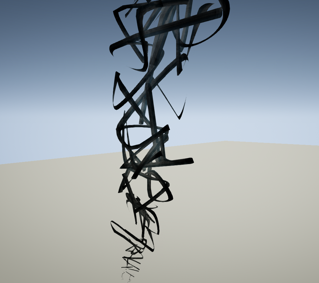
The Ribbon type data module indicates that the emitter should output trails - connecting particles to form ribbons. Particles are connected in the order of their birth. Therefore, the more erratic the initial velocity pattern of the particles, the more chaotic the ribbon.
The Ribbon type data module has the following properties:
| Property | Description | ||||||||
|---|---|---|---|---|---|---|---|---|---|
| Trail | |||||||||
| Sheets Per Trail | The number of sheets, rotated around the length of the trail, to render for the trail. | ||||||||
| Max Trail Count | The number of live trails allowed. | ||||||||
| Max Particle In Trail Count | The maximum number of particles that the trail may contain at any one time. | ||||||||
| Dead Trails On Deactivate | If true, trails are marked dead when the ParticleSystem is deactivated. This means the trails will still render, but no new particles will be spawned, even if the ParticleSystem is re-activated. | ||||||||
| Dead Trails On Source Loss | If true, the trail is marked dead when the source of the trail is 'lost', i.e. the source particle dies. | ||||||||
| Clip Source Segment | If true, the trail will not be joined to the source position. | ||||||||
| Enable Previous Tangent Recalculation | If true, the previous tangent will be recalculated each time a new particle is spawned. | ||||||||
| Tangent Recalculation Every Frame | If true, all tangents are recalculated every frame to allow velocity/acceleration to be applied. | ||||||||
| Spawn Initial Particle | If true, the ribbon will spawn a particle when it first starts moving. | ||||||||
| Render Axis | The 'render' axis for the trail (what axis the trail is stretched out on). The following options are provided:
|
||||||||
| Spawn | |||||||||
| Tangent Spawning Scalar | The tangent scalar for spawning. Angles between tangent A and B are mapped to [0.0f .. 1.0f]. This is then multiplied by Tangent Spawning Scalar to give the number of particles to spawn. | ||||||||
| Rendering | |||||||||
| Render Geometry | If true, the trail geometry will be rendered. This should typically be enabled as the trail is not visible otherwise. | ||||||||
| Render Spawn Points | If true, stars are rendered in the location of each spawned particle point along the trail. Used for debugging in Cascade. | ||||||||
| Render Tangents | If true, the tangent at each spawned particle point along the trail is rendered using a line. Used for debugging in Cascade. | ||||||||
| Render Tessellation | If true, the tessellated path between each spawned particle is rendered. Used for debugging in Cascade. | ||||||||
| Tiling Distance | The (estimated) covered distance to tile the 2nd UV set at. If 0.0, a second UV set will not be passed in. | ||||||||
| Distance Tessellation Step Size | The distance between tessellation points for the trail. This is used to determine how many tessellation points the trail has, and thus how smooth the trail is. The exact calculation is: |
||||||||
| Enable Tangent Diff Interp Scale | If this flag is enabled, the system will scale the number of interpolated vertices based on the difference in the tangents of neighboring particles. Each pair of neighboring particles will compute the following CheckTangent value: If CheckTangent is < 0.5, then the DistanceTessellationStepSize will be scaled based on the result. This will map so that from parallel to orthogonal (0 to 90 degrees) will scale from 0 to 1. Anything greater than 90 degrees will clamp at a scale of 1. |
||||||||
| Tangent Tessellation Scalar | The tangent scalar for tessellation. Angles between tangent A and B are mapped to 0 to 1. This is then multiplied by TangentTessellationScalar to give the number of points to tessellate. |