The Texture Color painting mode uses a generated mesh paint texture for static mesh components. For them to correctly display onto a mesh, this requires some additional setup in their materials with the MeshPaintTextureObject material expression and for the static mesh to have a suitable UV setup that works well for mesh texture color painting.
The sections below demonstrate how you should set up a material and mesh to work well with Texture Color painting.
Setting Up a Texture Painting Material
Follow the sections below to set up a material to use the MeshPaintTextureObject and MeshPaintTextureReplace material expressions.
To learn more about Texture Coloring and Mesh Paint Textures, see Getting Started with Mesh Texture Color Painting.
Adding a Mesh Paint Texture Object to a Material
The MeshPaintTextureObject material expression is used with a Texture Sample node to sample the generated mesh paint texture of a static mesh component. This material logic can be integrated into an existing material or used on its own.
Follow these steps to setup a material to sample a mesh paint texture associated with a mesh:
- Create a new material or open an existing material.
- Right-click in the material graph, and add a Texture Sample node.
-
Right-click in the material graph, and add a MeshPaintTextureObject node. Plug this into the Tex (Texture) input of the Texture Sample node.

-
On the Texture Sample node, set the UVs field to match the Mesh Paint Texture Coordinate Index on the static mesh or the Overridden Mesh Paint Texture Coordinate Index on a static mesh component.
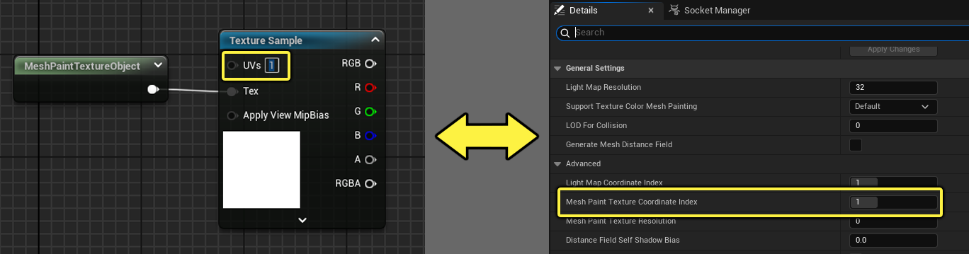
To learn more about how to set this up, see the section below for “Setting Up a Mesh for Texture Color Painting”.
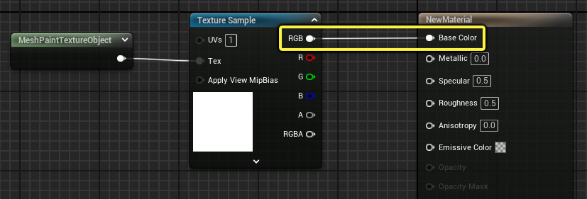
Once this part is set up in the material graph, you can connect the RGB output of the Texture Sample node to the Base Color input of the main material node. This setup will use just the mesh paint texture for the mesh’s material.
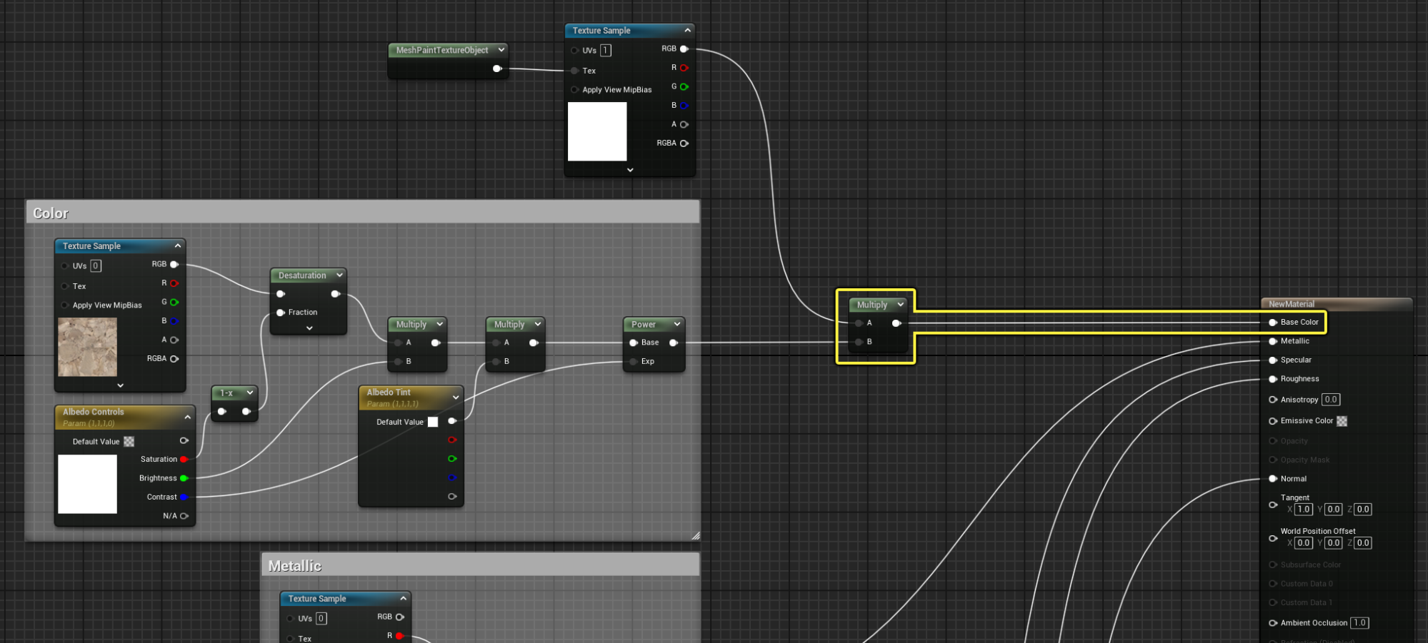
Alternatively, if you’re integrating this workflow into an existing material used with your mesh, you can use a Multiply with the material logic plugging into the Base Color input of the main material node. In this setup, the mesh paint texture would be used to tint painted areas of the underlying base material.
This setup can look like this:
Setting Up Fallback Logic for a Mesh Paint Texture Material
There are times where a material is applied to a mesh that doesn’t have a mesh painted texture or the platform doesn’t support virtual textures that are needed for mesh paint textures. In these cases, you want to have a fallback option for the material to correctly render.
Follow the steps below to set up some logic in the material graph to use an alternative path when a mesh paint texture isn’t available to sample:
- Right-click in the material graph, and add a MeshPaintTextureReplace node.
-
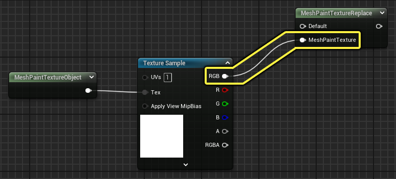
On the Texture Sample node with MeshPaintTextureObject node, drag off the RGB output and plug that into the MeshPaintTexture input of the MeshPaintTextureReplace node.
-
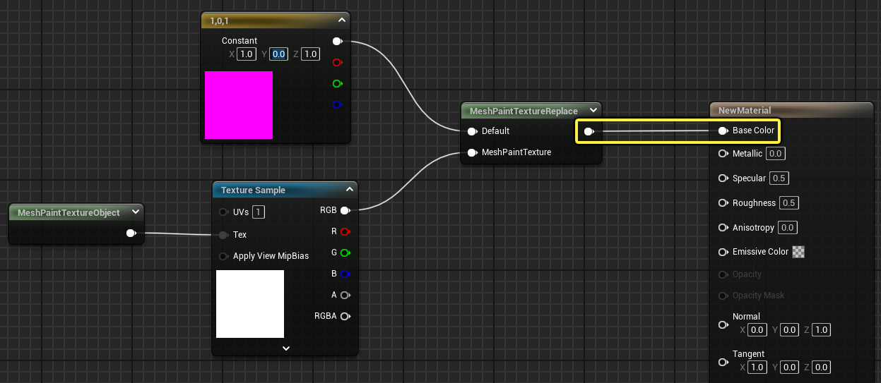
On the Default input of the MeshPaintTextureReplace, you can plug in any other material logic to be used in place of the MeshPaintTexture path. For simplicity, you could use a Texture Sample node or ConstantVector3 to set a color.

Once this part is set up in the material graph, you can connect the output pin on the MeshPaintTextureReplace node to the Base Color input of the main material node. This provides two simple paths: if the mesh using this material has a Mesh Paint Texture, that path will be used, otherwise the Default path is used.
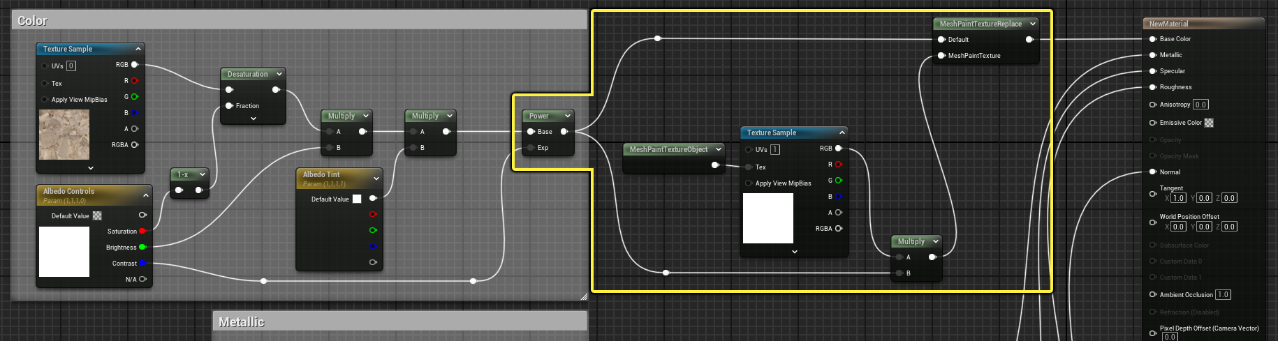
Alternatively, you could integrate this logic into your existing material graph by splitting the albedo output into the unaltered path plugged into the Default input, and the MeshPaintTexture path using the MeshPaintTextureObject logic with a Multiply node.
This setup can look like this:
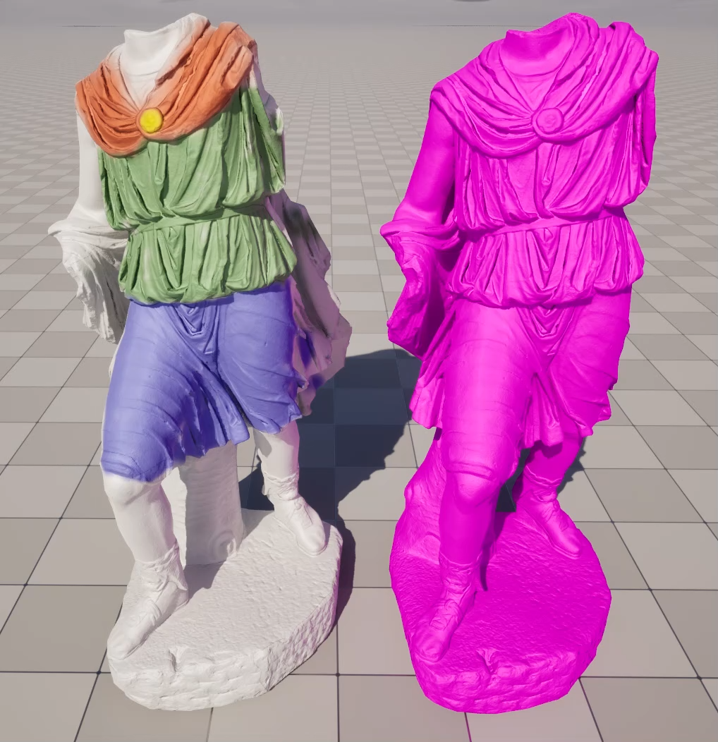
Below are examples of the two material graphs shown above with each showing a mesh with and without a mesh paint texture on the mesh but using the same material.
 |
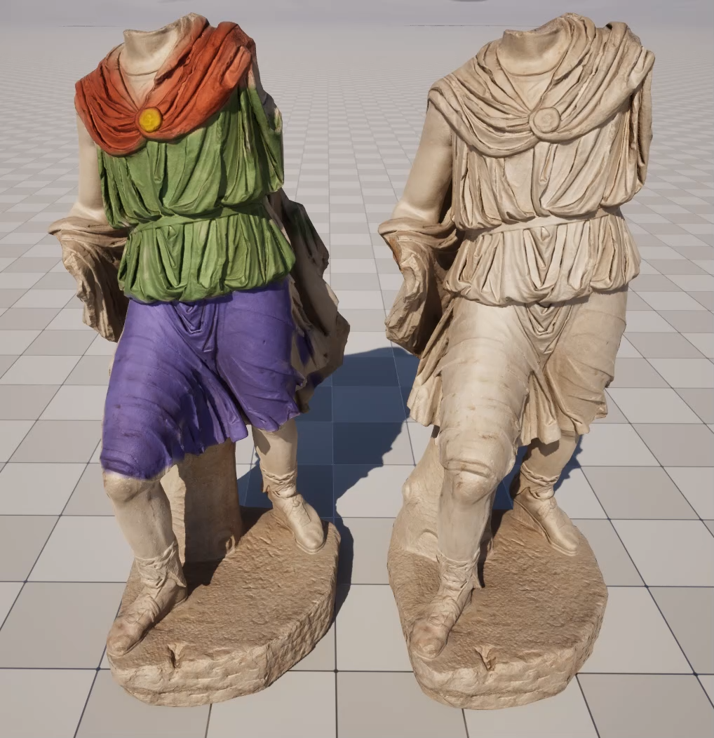 |
| The most basic MeshPaintTextureReplace. Left is the MeshPaintTexture path, and right is Default Path. | A MeshPaintTextureReplace setup integrated with an existing material as the Default texture. Left is the MeshPaintTexture path, and right is Default Path. |
Setting Up a Mesh for a Texture Painting Material
Follow the sections below to set up a mesh to correctly use Texture Color painting with a mesh paint texture. These sections will detail how to set up and assign suitable UVs and how they should be applied to the mesh’s material to work well with Texture Color painting.
Static Mesh Requirements
The UVs value on the Texture Samplenode using the MeshPaintTextureObject material expression should match the Mesh Paint Texture Coordinate Index of the static mesh. This ensures the correct UV of the static mesh is being used by its material to paint to the generated mesh paint texture.
To learn more about the MeshPaintTextureObject material expression, see the section above for "Setting Up a Texture Painting Material”.
Inspecting the Mesh UVs
To inspect a mesh’s UVs for use with texture color painting:
- Open a Static Mesh asset from the Content Browser.
-
In the Static Mesh Editor toolbar, use the UV dropdown to see what UV channels are available. Select one from the list to inspect it.
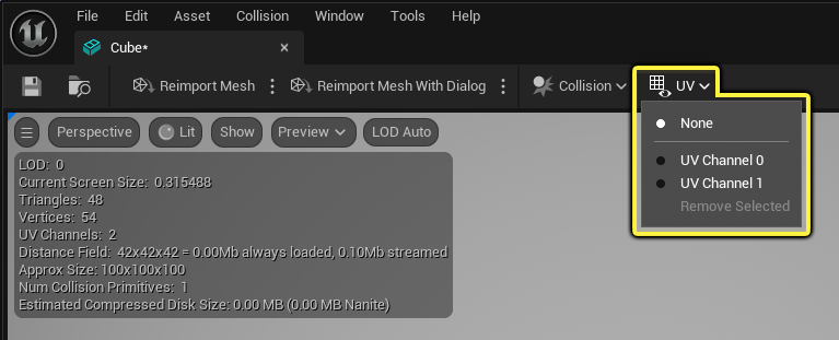
When looking at whether a UV is suitable for texture color painting, you’ll want to see if it has any overlapping, tiling, or repeating UVs. If it does, you’ll want to have a UV channel that lays out the UV charts so that each part of the geometry has a unique ID.
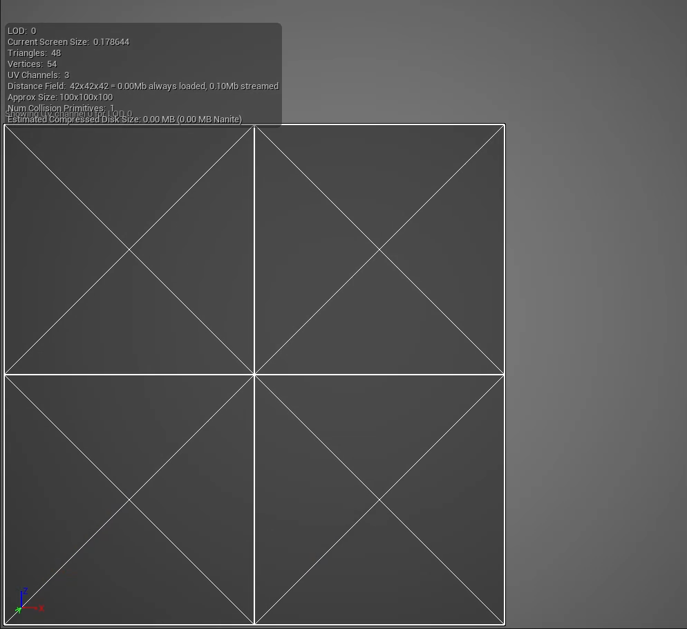
Take for example the UV below of the Cube shape included with Unreal Engine:
- UV Channel 0 has overlapping faces where each side of the cube is laid on top of one another and fills the entirety of the UV space.
- UV Channel 1 has been generated in the Static Mesh Editor so that no UV charts overlap with another one, all six faces of the cube get their own spot within the UV space.
 |
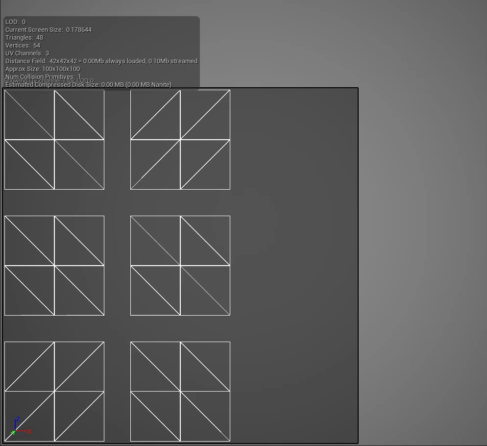 |
| Unsuitable UV for Texture Color Painting. | Suitable UV for Texture Color Painting. |
To see why these are unsuitable and suitable, below are the results when painting on a mesh with overlapping, repeating, or tiling UVs compared with one that has unique IDs for each face of the mesh.
 |
 |
| Results of an unsuitable UV for Texture Color Painting. | Results of a suitable UV for Texture Color Painting. |
Generating a UV for Texture Color Painting
To generate a new UV set in the Static Mesh Editor:
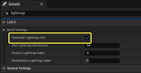
- Go to the Details panel and scroll down to the LOD 0 category, and expand the options for Build Settings.
-
Check the box next to Generate Lightmap UVs.
-
These are some other optional settings you can change that can benefit your mesh when generating a UV:
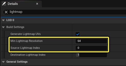
- Min Lightmap Resolution sets the target resolution of the UV. This sets the spacing between the UV charts as they are laid out in the available UV space. For example, a resolution of 64 would leave more space between UV charts than 256, meaning that the UV charts can be more tightly packed and scale some charts larger.
- Source Lightmap Index uses this UV channel to generate a UV from. Some meshes may have more than one UV, so you can choose one that is most suitable for generating a new UV from. In most cases, UV0 is the best candidate for generating a new UV from.
-
Set a value (UV Channel) you want to generate the lightmap UV for with the Destination Lightmap Index.
This should automatically be set to the next available UV channel slot to not affect any that are already created for the mesh. You can change this or use this value as needed for your mesh.
- Click Apply Changes.
To see the results, you can use the UVs dropdown in the static mesh editor toolbar. Select the UV channel you want to view.
Setting the UV for Texture Color Painting
To set the UV that will be used for texture color painting:
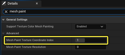
- In the Details panel, navigate to the General Settings category.
-
In the text field for Mesh Paint Texture Coordinate Index, enter a number that matches the UV channel you want to use for mesh texture painting. For example, UV Channel would be 0, UV Channel 1 would be 1, and so on.
This coordinate index will need to be set on the UVs input of the Texture Sample node using the MeshPaintTextureObject material expression for this setup to be correctly utilized, see the section above for “Setting Up a Texture Painting Material” to get started.

If you’re seeing painting inconsistencies that look related to the UV, check that the Mesh Paint Texture Coordinate Index and Texture Sample node with the MeshPaintTextureObject expression is using the same UV coordinate.