
The Modeling editor mode, refered to as Modeling Mode, provides a toolset for creating, sculpting, and editing meshes directly in Unreal Engine. You can use it to create new meshes, rapidly prototype level geometry, and edit existing models to add variety to your world. This overview outlines the core concepts behind these tools and their workflow, how to access them, and the basics of working with them.
Accessing Modeling Mode
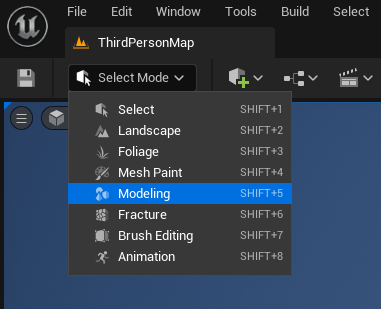
To use the Modeling Mode, click the Select Mode dropdown, then select Modeling. Alternatively, press SHIFT+5 to immediately switch to this mode.
If Modeling does not appear in the Mode dropdown, ensure the editor is enabled in your Plugins.
Edit > Plugins > Modeling Tools Editor Mode

The Mode Toolbar (1) and the Modeling panel (2) will appear.
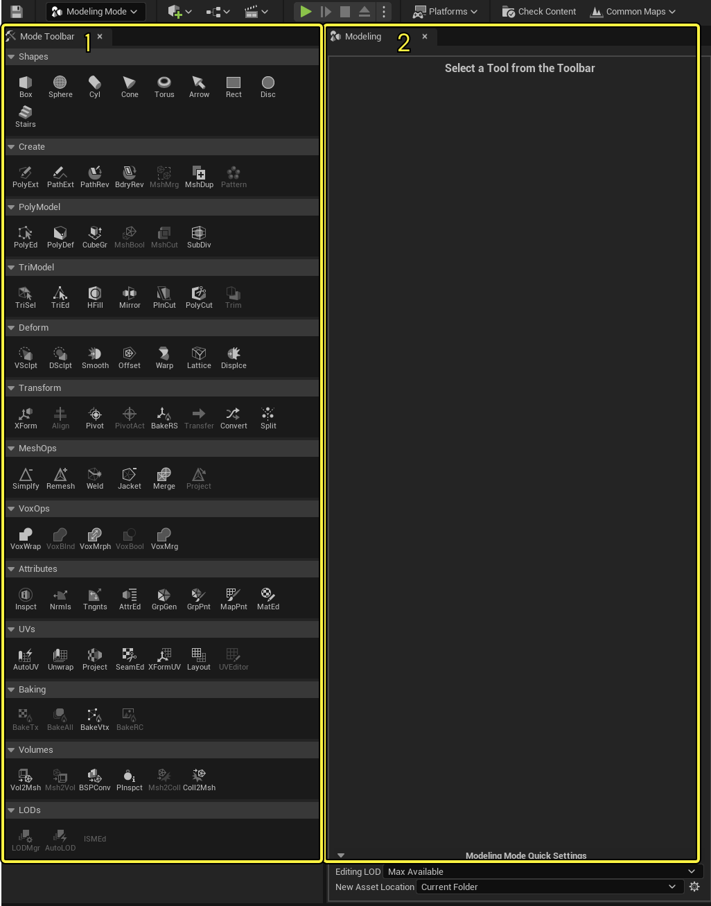
If you select a tool from the Mode Toolbar, its properties will appear in the Modeling panel. You can use this panel to configure your tool's output before you commit to creating a mesh or making changes.
Help Line
A panel with additional tooltips, such as hotkey commands, is available in the Bottom Toolbar of the Level Editor when using Modeling Mode.
Click image to expand.
Understanding Key Concepts
Although many tools in Modeling Mode are similar to their counterparts in other modeling software, there are a few essential differences in how Modeling Mode structures mesh editing that you should know before you begin working with it.
Terminology
The modeling tools are usable when you are working on various types of Actors in Unreal Engine (UE), for example, a Static Mesh, a Dynamic Mesh, or a Volume. These are collectively referred to as "a mesh" or "meshes", except when a tool is only usable for a specific Actor type.
Triangles and PolyGroups
Unreal Engine renders all models as triangulated meshes. In other words, when you import or create a mesh, its surface is automatically broken up into triangles (tris) regardless of whether they were already defined in a different environment. This conversion to triangles provides several guarantees:
- UE can't import or create a model that it can't render.
- UE's rendering is portable across all platforms, as all graphics drivers universally recognize triangles.
- UE does not need to spend time and resources resolving quadrilateral (quad) polygons and n-gons (polygon with more than 4 sides) into triangles at runtime.
In the Modeling Mode, you can edit the triangles of your model using the tools in the TriModel category. These are the most low-level editing tools, based entirely around selecting and editing tris and vertices directly.
Although Unreal Engine does not natively recognize quads or n-gons, it does support PolyGroups, which can mimic those features. PolyGroups are arbitrary collections of triangles that various tools in Modeling Mode can define. You can then manipulate these groupings using the PolyModel tools.
When creating a mesh using the Shapes category, you can configure the PolyGroups of your new mesh using the PolyGroup Mode setting.
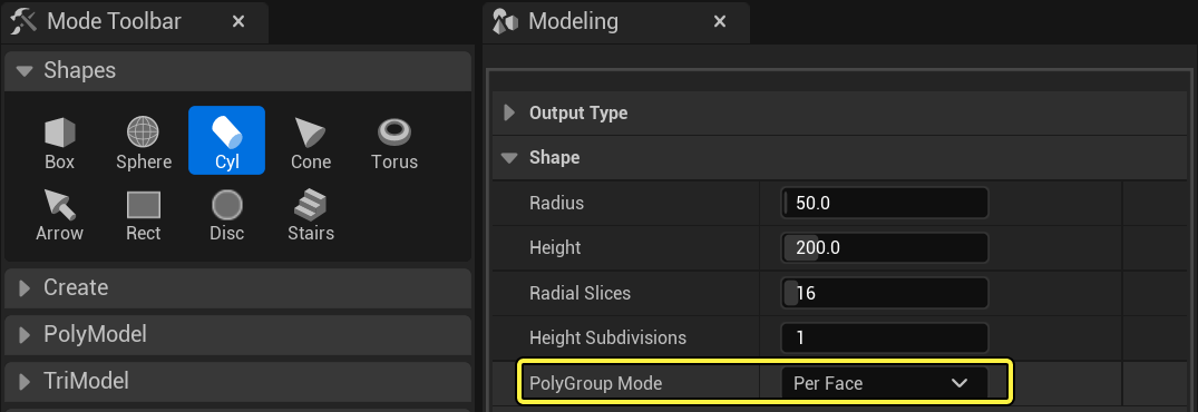
Additionally, you can use the TriSel (Triangle Selection), GrpGen (PolyGroup Generation), and GrpPnt (PolyGroup Paint) tools to assign PolyGroups.
Click image to expand.
You can then use PolyGroups for traditional modeling using the PolyEd (PolyGroup Edit) tool and to create UV islands using the UV tools.
To learn more about creating and using PolyGroups, see Understanding PolyGroups.
Tools, Undo History, and Accepting Changes
Most tools in the Modeling Mode will not apply changes to meshes immediately. Instead, the tool previews the mesh with your changes in place, and a prompt displays a Cancel and Accept button.
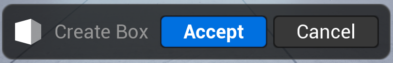
If you exit Modeling Mode or press Cancel, the changes are discarded, and the mesh will revert to what it looked like before you started editing it. When you press Accept, you exit the tool, and all the changes you made to the mesh while using the tool are applied to the underlying mesh. Changes are also applied when you switch from an active tool session to another tool.
While you can generally undo or redo individual changes inside a particular tool, once you accept the changes, the Undo system only tracks the state of the mesh before and after the tool is active. For example, you can undo each brush stroke while using the VSclpt (Vertex Sculpt) tool. Once you click Accept, exiting the sculpt tool, you can only Undo the combined result of all the brush strokes — reverting your mesh to its state before you started the tool.
Meshes, Assets, and Project Settings
The type of Actor you choose to represent your mesh determines how Modeling Mode handles the creation and editing process. When creating a new mesh using the Shapes or Create category, you use Output Type to select the desired Actor. You can choose between the following Actors as your target mesh:
- Static Mesh
- Represents your model and is saved in the Content Browser. An instance of the mesh is placed in the Level.
- Dynamic Mesh
- Represents your model and is saved in the Level only.
- Volume
- Represents an area that triggers a behavior and is saved in the Level only.
These types have various use cases and benefits. You can change the Actor type of the current mesh using tools such as Convert and Transfer. Using Project Settings, you can configure the creation and selection of meshes, as well as the saving of Assets.
Refer to the Working with Meshes documentation to continue learning about how output types are handled and how to adjust settings for your workflow.
Using Modeling Mode
Creating a Mesh
To create a new mesh, click any of the tools in the Shapes category and move your mouse cursor into the Viewport. A template of the shape you selected will follow your cursor and snap to the Level grid. Click where you want to add the mesh in your game's world and the editor will create the shape with the parameters you configured in the Modeling panel.
You can also create meshes using tools in the Create category. For example, the PolyExt tool can draw a footprint for a mesh, then extrude it to create a custom 3D shape.
Several tools, such as PolyExt and PathExt, use a grid to draw shapes. To control the position of the grid, Ctrl + Click your desired location.
Editing a Mesh
Most of the other tools in Modeling Mode are built around editing an existing mesh in your game's world. For example, if you select TriEd or PolyEd, then click a mesh, you can choose its components and perform modeling operations.
Individual operations in the TriEd (Triangle Edit) and PolyEd tools, such as Extrude, Push Pull, or Cut Faces, appear in the Modeling panel. After you make your edits, click the Accept button to finalize your changes, or click Cancel to discard them.
You can select any mesh in your world and edit it using these tools, including meshes that were not created in Modeling Mode. For example, you can use the Lattice tool on a high-quality Static Mesh to quickly reshape it.
If you are going to edit a high-quality model, it is highly recommended that you duplicate the asset using the Dupe tool to preserve the original mesh.
Gizmo
Modeling Mode has a dedicated gizmo for unique and quick mesh transformations. By default, scale, rotate, and translate (move) are combined into one gizmo.
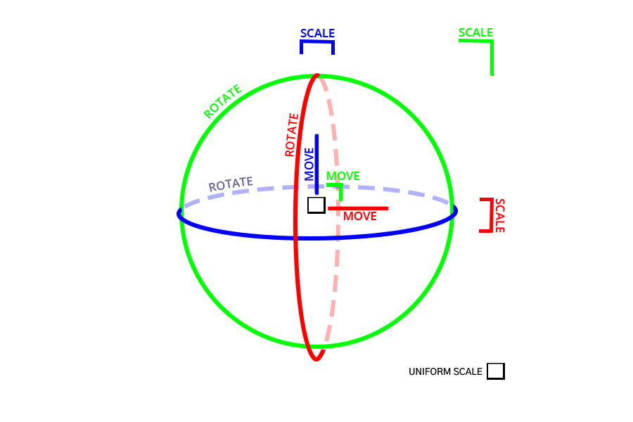
To use an individual modeling gizmo consistent with the Level Editor's standard translation, rotation, and scale, disable Combined Gizmo using the settings icon in Modeling Mode Quick Settings.
Click image to expand.
In addition to the modeling gizmo's structure, you can:
- Switch between relative and absolute grid snapping by toggling World Grid Snapping.
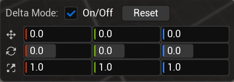
- Use the Transform Panel for numerical input for world space and local delta values.
The Transform Panel shows directly in the Viewport and is available for several modeling and UV tools.
Gizmo Hotkeys
You can use the hotkeys listed in the table depending on the tool and operation. Specific modeling tools have additional gizmo attributes, such as a repositionable grid for PolyExt, PathExt, and the Patten tool. Use the Help Line to indicate when you can use these hotkeys.
| Hotkey | Description |
|---|---|
| Ctrl Hold | Align the selected gizmo transform to the scene. Excludes scale. |
| Crtl + Click | Reposition the gizmo grid. |
| Middle Mouse + Translate | Reposition the gizmo. |
| Q | Toggl orientation lock. Only active with the local coordinate system. |
Tool Categories
| Category | Description |
|---|---|
| Shapes | Creates a new mesh using a selection of predefined primitives. |
| Create | Build meshes from paths or existing geometry. |
| PolyModel | Perform granular editing using a mesh's PolyGroups. Only useable if the model has more than one PolyGroup. |
| TriModel | Perform granular editing using a mesh's triangles. |
| Deform | Alter or distort a mesh as a whole or in specific areas. |
| Transform | Adjust the placement or representation of a mesh. |
| MeshOps | Optimize a mesh's geometry. |
| VoxOps | Convert a mesh into voxels to perform volumetric operations before converting it back into a mesh. |
| Attributes | Inspect and adjust the secondary properties of a mesh. |
| UVs | Edit the UV coordinates of a mesh, changing how textures are mapped to the surface. |
| Baking | Generate textures and vertex color data for meshes. |
| Volumes | Convert between volume, mesh, Binary Space Partitioning (BSP), and Simple Collision representations. You can also inspect the collision and physics properties of the selected mesh. |
| LODs | Edit and manage the levels of detail (LODs) for a mesh. |
To learn more about these categories and their specific tools, see Modeling Tools.
Geometry Scripting
Geometry Scripting is an Unreal Engine plugin containing a set of Function Libraries that provide the ability to generate and edit mesh geometry via Blueprints and Python. Geometry Scripting UFunctions and Blueprint Nodes operate on UDynamicMesh objects, which are objects created using the FDynamicMesh3 C++ triangle mesh data structure. This is the same data structure used by the Geometry Processing plugin and Modeling Mode.
Geometry Scripting can be used in Editor Utility Widgets and Asset Actions to create custom mesh analysis , processing , and editing tools. You can also use it in Actor Blueprints to create procedural objects and implement complex geometric queries.
For more information on using Geometry Scripting, see Geometry Script Users Guide.