
This tutorial guides you through the configuration setup for an inner frustum split on a nDisplay ICVFX Camera using SMPTE 2110.
With the introduction of SMPTE 2110 support, you can now dedicate an entire nDisplay render node to just the inner frustum. Unreal Engine 5.4 introduces the ability to render the Inner Frustum with even more hardware resources, across both multiple nodes as well as multiple GPUs (similar to a Multi-Process deployment), to produce the highest quality Inner Frustum possible. As new cameras increase in resolution and volumes increase in size, the system can scale with the needs of modern productions.
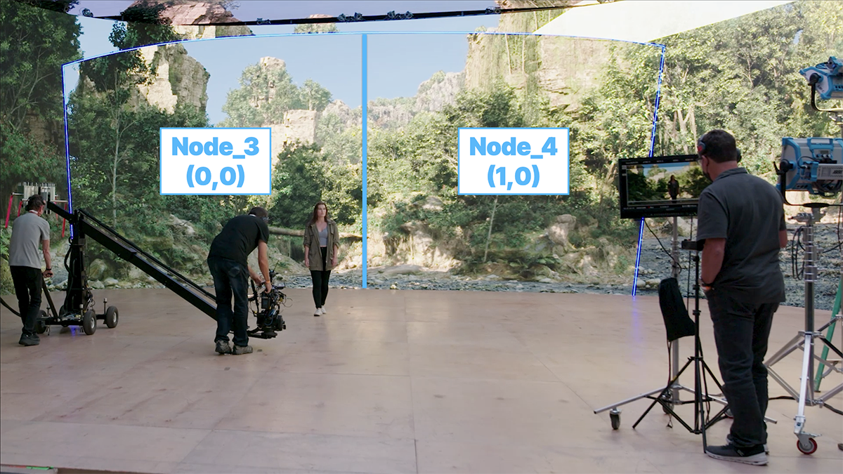
Using multiple nodes for an inner frustum split on-set for an ICVFX shoot.
Configuration
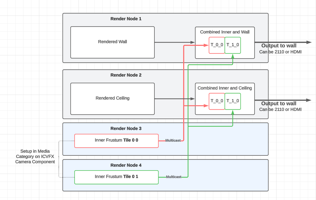
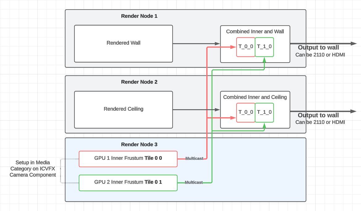
A sample configuration diagram for an inner frustum split using nDisplay and SMPTE 2110.
-
Create an nDisplay configuration.
-
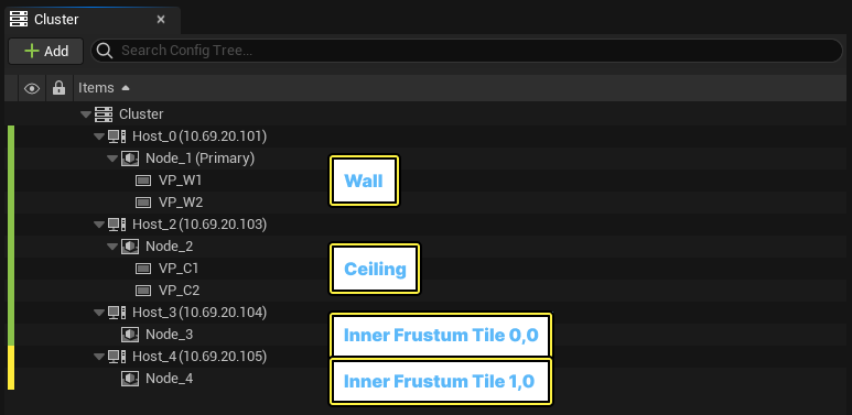
Add a Node layout that reflects the deployment of your setup.
-
Nodes 1 and 2 render the wall and ceiling, respectively.
-
Nodes 3 and 4 render the inner frustum tiles (0,0) and (0,1) respectively, and both have the Headless Rendering setting enabled (set this in their configuration accordingly), which means they render no (outer) viewports.
-
-
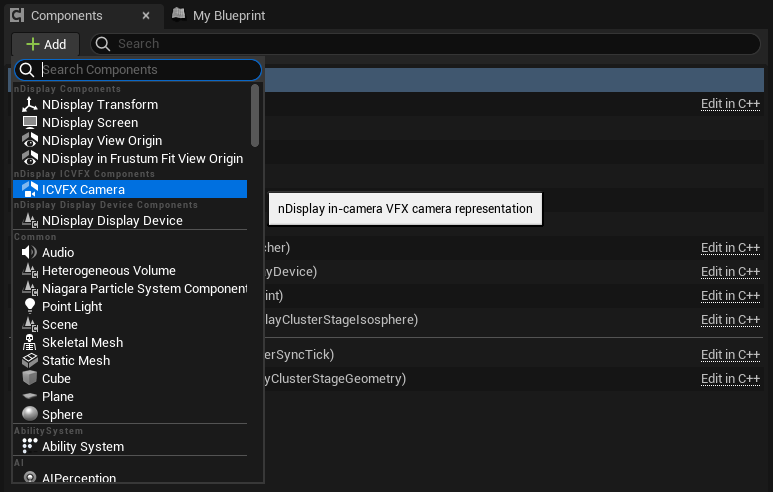
Add an ICVFX Camera component.
-
Select the ICVFX Camera component and go to the Details panel.
-
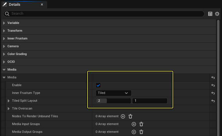
Enable Media, and select Tiled as the Inner Frustum Type.
-
Select the number of tiles in the horizontal (x) and vertical (y) directions. In this example, the total number of tiles to render is two (2) – two tiles horizontally and one vertically.
-
-
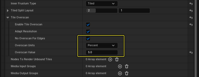
Enable Tile Overscan to use overscan to improve tile blending.
-
Enable No Overscan for Edges.
-
Set the Overscan Value to 5% or higher.
-
-
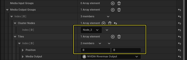
Under Media Output Groups, create a group for each set of nodes that will render Inner Frustum tiles. In this example, the first tile (0,0) will render on Node_3 and the second tile will render on Node_4 (1,0).
-
Select NVIDIA Rivermax Output as the Media Output. This means you can set up the SMPTE 2110 stream with the specified parameters.
Most properties will be initialized using the default parameters.
-
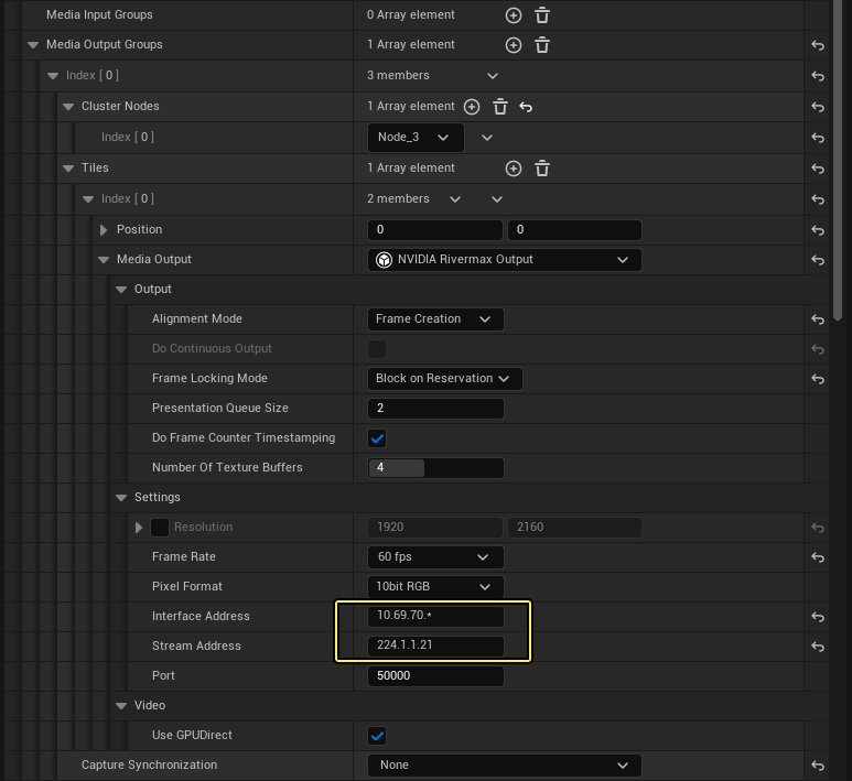
The Resolution is automatically set based on the tile layout, and you should not need to set specific values.
-
Set the correct Interface Address and Stream Address for your network.
-
You must set the Frame Rate higher than the rendering rate. If the bandwidth permits it, it should be at least twice as high.
-
If you want to use GPU Direct, Unreal Engine 5.4 supports it when Frame Locking Mode is set to Block on Reservation and Alignment Mode is set to Frame Creation, so set those values accordingly.
-
Leave Capture Synchronization set to None.
-
-
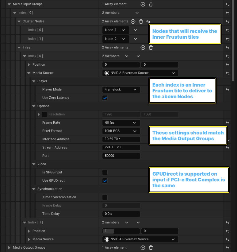
Under Media Input Groups, specify the nodes that will receive the inner frustum tiles.
-
Create a Media Input Group for each group of outer viewports that will receive the inner frustum tiles. In this example, there are two tiles, and both should be visible by Node_1 (wall) and Node_2 (ceiling).
-
Add the number of tiles to match the number configured to render in Media Output Groups. Each index is an inner frustum tile to deliver to the Nodes above.
-
For each tile, specify the relevant tile coordinates, add an NVIDIA Rivermax Source, and match the stream settings of the Media Output groups.
Some deployments might want to specify a different Interface Address or remove the wild card. Ensure the frame rate matches between input and output.
-
GPUDirect is supported on input if the PCI-e root complex is the same.
-
Multi-Process Inner Frustum Split
If you have a deployment with render nodes that have multiple (2 or more) GPUs, you might choose to combine a Shared Memory/Multi Process deployment with SMPTE 2110 and an inner frustum split. This means you can devote more resources to each viewport and inner frustum tile, while reducing the total number of render nodes required for the deployment.
In the following example, the same setup as in the previous example is laid out with 3 hosts instead of 4, with the outer viewports no longer sharing the same process/GPU:
-
Each viewport is rendered on its own Node/GPU on the same host, and the configuration uses both shared memory and SMPTE 2110 media.
-
Each inner frustum tile is rendered on its own node/GPU on the same host, and the configuration shares with SMPTE media only.
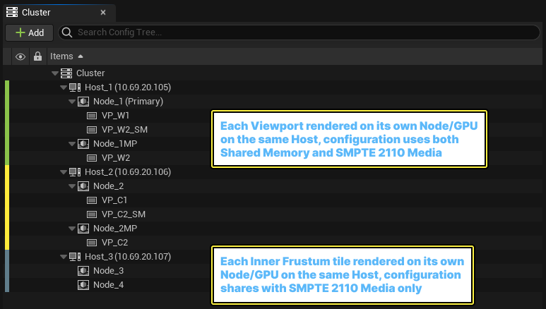
The hosts and nodes for a multi-process inner frustum split using nDisplay and SMPTE 2110.
A sample configuration diagram for a multi-process inner frustum split using nDisplay and SMPTE 2110.