Often when creating a film or cinematic, you need a way to better highlight the silhouette of a character or set piece. This lighting technique is referred to as rim lighting, or edge lighting, and involves adding additional lights to help differentiate the character's silhouette from the background. While this works nicely for film, adding additional lights to any 3D scene adds extra complexity that can quickly become difficult to manage.
Unreal Engine offers a solution to this at the Material level. Using Fresnel, artists can simulate rim lighting in the Material of a character or prop, giving them more control over the look and feel of the effect. Fresnel is an inherent property of many naturally occuring Materials, including glass, water, and some types of fabric and paint. The techniques in this tutorial will help you simulate those Materials more accurately.
Fresnel
Fresnel is the term used to describe how the light you see reflects at different intensities based on the angle of view. For example, if you are standing over a pool looking straight down, you will not see a lot of reflections on the water. As you move your head so that the water in the pool becomes parallel to your eye level, you will begin to notice more and more reflections on the surface of the water. Water and glass both exhibit strong Fresnel tendencies, meaning they appear relatively transparent when viewed straight-on, and reflect more light at glancing angles.
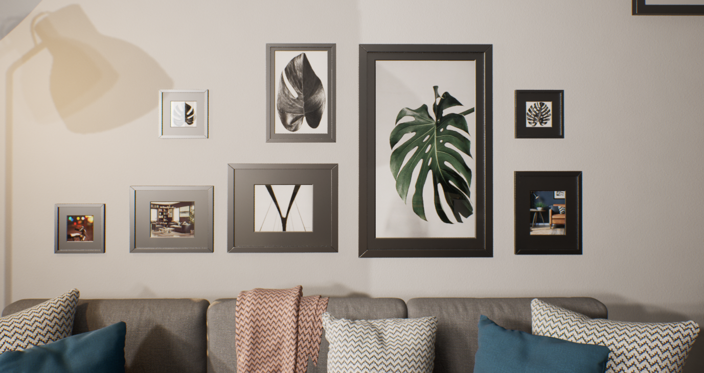
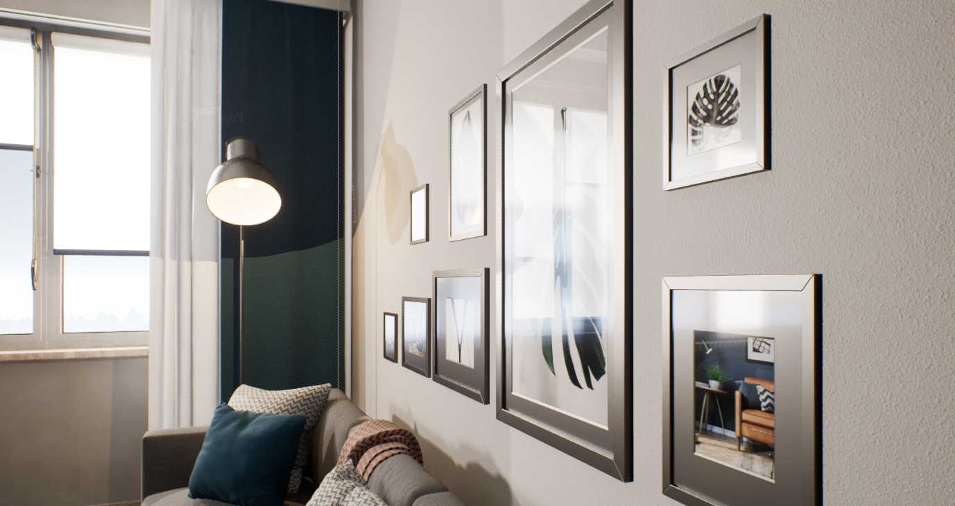
Note how the glass in the picture frames is transparent when viewed straight on, and shows more reflections when viewed from the side.
In Unreal Engine, the Fresnel Material Expression calculates a falloff based on the dot product of the surface normal and the direction to the camera. When the surface normal points directly at the camera, a value of 0 is output meaning there should be no Fresnel effect happening. When the surface normal is perpendicular to the camera, a value of 1 is output meaning the full effect of the Fresnel should be taking place. The result is then clamped to [0, 1] so you do not have any negative color in the center. The following image demonstrates this concept.
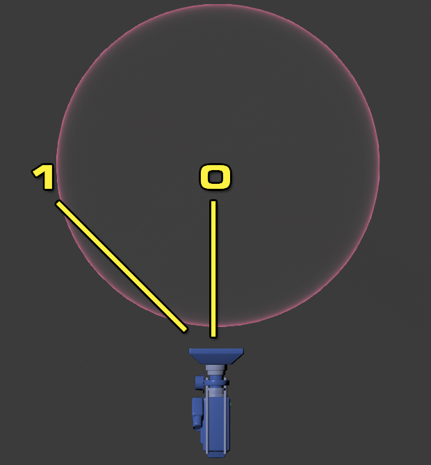
In the middle of the sphere (labeled 0), there is no Fresnel effect. This is because the camera is pointing directly at the surface normal. Toward the edges of the sphere (labeled 1), the surface normals are increasingly perpendicular to the camera and the Fresnel effect becomes more and more visible. This creates an impression that the edges of the sphere are illuminated.
Fresnel Node Breakdowns
When searching for "Fresnel" in the Palette or contex menu, you will find there is a Fresnel Material Expression under Utility and a Material Function under Vector Ops. While these two nodes are used for the same purpose, they differ in how you set them up for use.
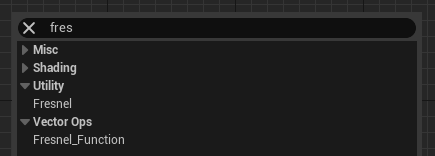
Fresnel Material Expression
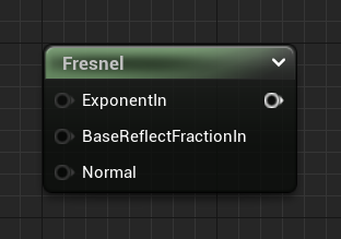
The Fresnel Material Expression found under Utility is the one used in this tutorial, and is the simpler out of the two options to configure. It is highly recommended you use this version to begin with, and only use the Fresnel Material Function once you better understand how the node works.
| Property | Description |
|---|---|
| ExponentIn | This input controls the falloff of the Fresnel Effect. |
| BaseReflectFractionIn | This specifies the fraction of specular reflection when the surface is viewed from straight on. Setting this to a value of 1 effectively disables Fresnel. |
| Normal | You can input a normal map to change the way the Fresnel effect is rendered. Normal maps must be Transformed from Tangent Space to World Space (see below). |
There are three ways to adjust the values in the Fresnel Material Expression.
-
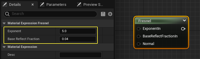
When the node is selected in the Material Graph you can enter values in the Details Panel.
-
You can also connect Constant or Scalar Parameters to the inputs.
-
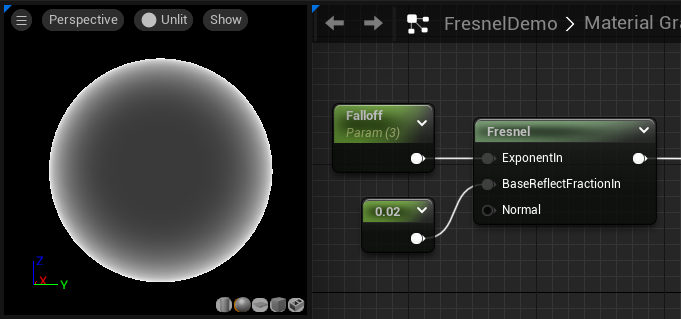
You can attach a normal map to the Normal input to change the appearance of the fresnel effect. If you use a normal map texture, you must pass it through a TransformVector expression before connecting it to the Normal input. This will transform the normal map from Tangent Space to World Space. Without this Transform, the normal map may not influence the Fresnel the way you intend.
Click to enlarge image.
Fresnel Material Function
The Fresnel_Function Material Function in the Vector Ops category is a highly customizable version of Fresnel that provides control over several different aspects of the Fresnel effect. This added functionality has its drawbacks, as incorrect settings could lead to artifacts or errors in how the Fresnel effect is rendered.
You should only use this Material Function if the Fresnel Material Expression under Utility does not yield the results you are looking for.
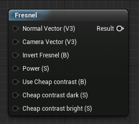
| Property | Description |
|---|---|
| Normal Vector (V3) | Here you can input a Normal to modify the way the Fresnel effect is rendered. You must pass a normal map through a Transform node (Tangent Space to World Space) for accurate results. |
| Camera Vector(V3) | Manually change the camera vector that is used to determine the Dot Product between the Camera and the surface normal. |
| Invert Fresnel(B) | Inverts the effect of the Fresnel. This is useful if you want the Fresnel to only be applied in the center or at the edges. |
| Power(S) | Input a Scalar to control the extent (or falloff) of the Fresnel effect. Entering larger numbers will tighten up the areas affected. Smaller numbers mean the Fresnel node affects a larger portion of the surface. |
| Use Cheap Contrast(B) | When enabled, the Fresnel node uses a cheaper method for calculating contrast between lights and darks. |
| Cheap Contrast Dark (S) | This controls how dark the Fresnel will be. This will only have an effect if Use Cheap Contrast is enabled. |
| Cheap Contrast Bright (S) | This controls how bright the Fresnel effect will be. This will only have an effect if Use Cheap Contrast is enabled. |
| Clamp Fresnel Dot Product (B) | Clamps the result of the Fresnel Dot Product between 0 and 1. This is true by default, but you can override it with a Static Bool set to false. |
How to Use Fresnel in your Material
Use the following steps to create a Material that uses Fresnel.
-
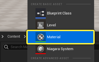
Right-Click in the Content Browser and select Material from the Create Basic Asset section in the context menu. Once the Material is created, name it FresnelMaterial.
-
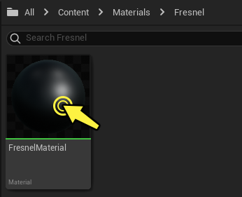
Open the new Material by double-clicking the thumbnail in the Content Browser.
-
Expand the Palette or right-click in the Material Graph to display the context menu. Search for the following Material Expression nodes and add them to your graph.
Node Name Amount Vector Parameter Node 2 Scalar Parameter Node 2 Fresnel Node 1 When completed, your Material Graph should look like this.
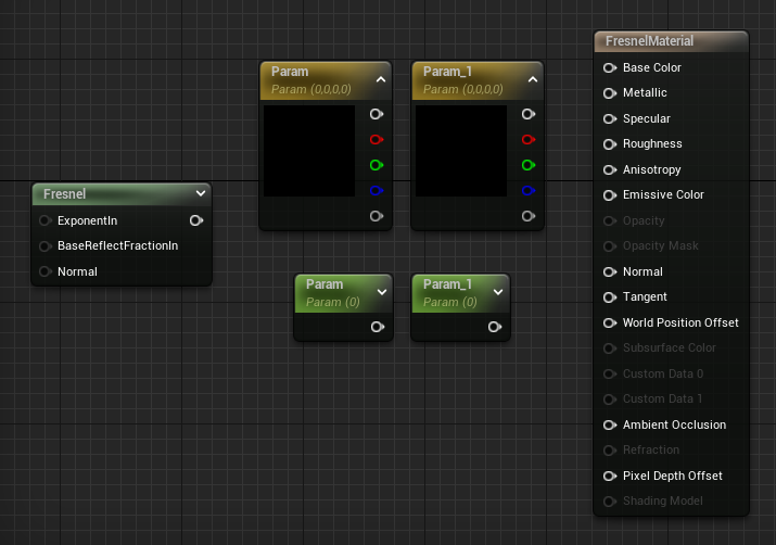
When you search for the Fresnel Material Expression, you will find two different Fresnel nodes to choose from. This tutorial uses the Fresnel Material Expression found in the Utility category.
-
Rename all the Scalar and Vector Parameter nodes, and set their default values in the Details Panel.
Name Default Value Fresnel Color 1.0, 0.0, 0.0, 0.0 Base Color 0.5, 0.5, 0.5, 0 Fresnel Falloff 8 Roughness 0.5 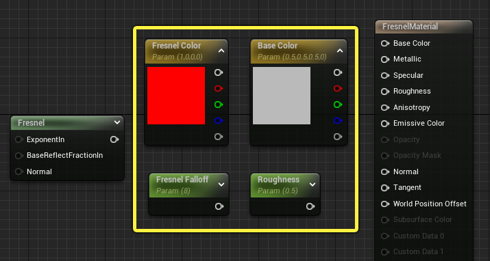
-
Add a Multiply node to the graph and then connect all the Material Expressions, using the image below as a guide.
Click image to enlarge.
-
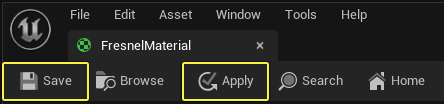
Click Apply in the toolbar to compile the Material, and then click Save.
-
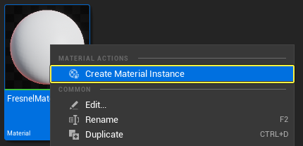
After you compile and save the Material, close the Material Editor and locate the FresnelMaterial asset in the Content Browser. Right-click the thumbnail and select Create Material Instance in the context menu.
-
Double-click the Instance to open it in the Material Instance Editor. Enable the parameters you want to override by checking the box next to each parameter name. Once the parameters are enabled, you can modify the values to change color and appearance of the Fresnel effect.
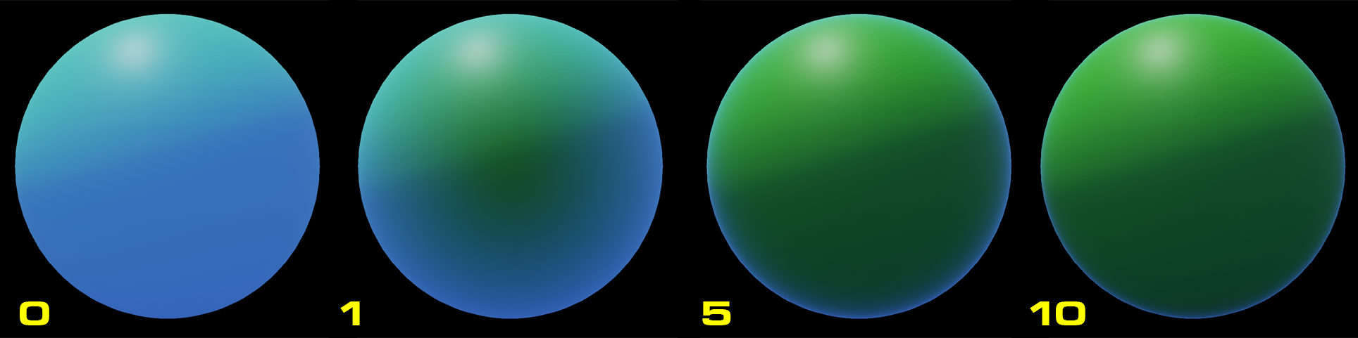
Remember that inputting larger numbers into Fresnel Falloff will push the Fresnel effect closer and closer to the edges, while lower numbers will bring the effect closer to the center. Here is an example of what happens when the Fresnel Falloff value is increased from 0 to 10. Notice how as the number increases, the blue color is pushed closer and closer to the edges of the sphere.
Fresnel and Normal Maps
Because Fresnel is calculated based on the surface normal of a face, you can use a normal map to influence the way the Fresnel effect is distributed across your Material. The Fresnel node works by checking whether or not the surface normal is perpendicular to the camera. If it is perpendicular to the camera, the Fresnel effect is visible. On a smooth sphere, this means the Fresnel effect only occurs at the edges.
However, when a Normal map is introduced, the surface normals are modified in such a way that there may be undulations and contours within the silhouette of a mesh. This means the Fresnel effect can highlight or emphasize details that would not be visible if the surface normals were smooth.
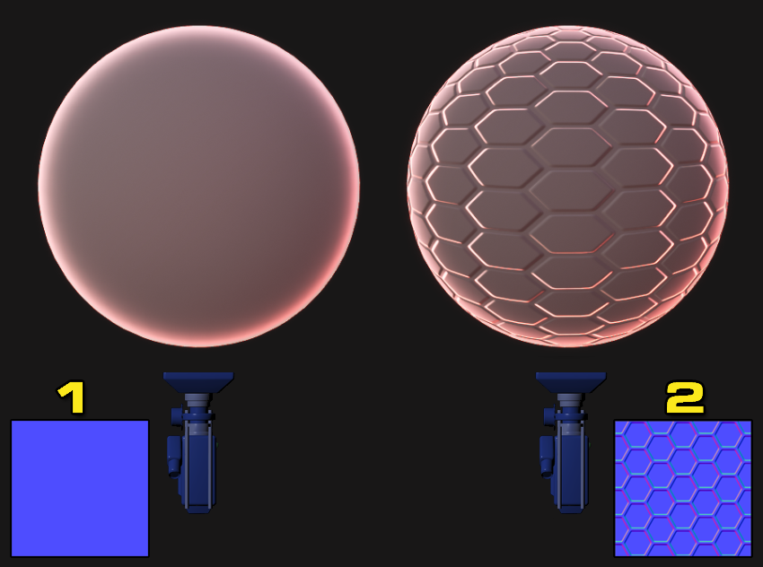
For a visual example of how this works, consider the two images below. The image on the left (1) shows what the Fresnel node will output with a flat surface normal. The Fresnel effect is only visible at the edges of the sphere. On the right (2), a normal map is input, which drastically changes the surface normals of the mesh. The Fresnel effect is now visible along the contours defined in the normal map.
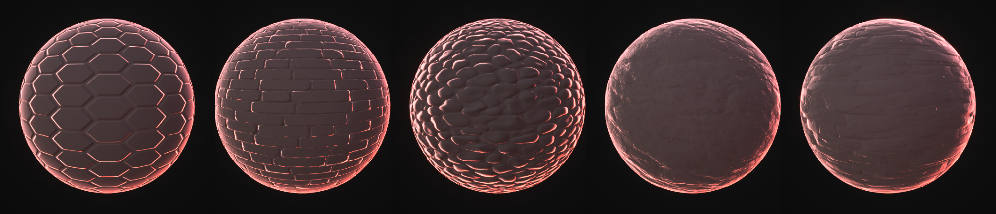
The image below shows how different normal maps affect the Fresnel in different ways.
The Material used in the comparison above was the same Material that was created before but with the following modifications.
- The Material's Blend Mode was changed from Opaque to Translucent.
- In the Details Panel, the Translucency Lighting Mode was changed from Volumetric Non Directional to Surface Translucency Volume.
- The Multiply output that was plugged into the Emissive Color input was also plugged into the Opacity input.
- A new 2D Texture Sampler was added and plugged into the Normal input. Tech_Hex_Tile_N from the Starter Content was used as the Normal texture.
- A new Scalar Parameter was added and multiplied by a Texture Coordinates expression to implement some basic uniform titling on the Normal map.
You can also pass a normal map into the Normal input on the Fresnel node. This is particularly useful if you want the normals of the Fresnel effect to be different from the normals of the underlying Material. For example, you could use the Fresnel node to display something like an energy shield on a Material, but still have that Material look normal when the shield is not active.
To achieve this using the Material above, make the following modifications to the Material.
-
Add the T_Brick_Clay_New_D texture from the Starter Content, and plug it into Base Color and Roughness.
-
Change the Normal input so that it uses T_Brick_Clay_New_N, which you can also find in the Starter Content.
-
Search for a Transform Material Expression node and add it to the Material graph. Make sure that it is set to transform from Tangent Space to World space.
-
Connect the old Normal map texture node into the input of the Transform node and connect its output into the Normal input on the Fresnel node.
When completed, your Material should look like the graph below.
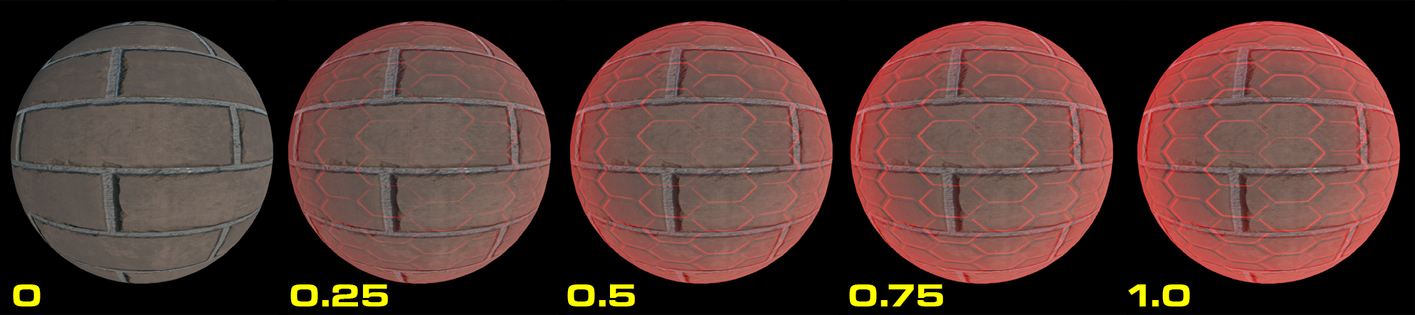
Now the surface normals in the Fresnel node are completely different from the surface normals in the brick texture. The Fresnel effect looks like a translucent layer on top of the bricks. If you think the effect is too strong, you can go one step further by adding a Multiply node and Scalar Parameter to control the intensity of Fresnel effect. Here is how you can implement an intensity control in the Material.
By adjusting the Fresnel Intensity parameter, you can control the intensity of the Fresnel effect on the surface. Setting the value to 0 turns off the effect, and setting it to anything else will gradually increase the visibility of the Fresnel effect like below.
Input Blending
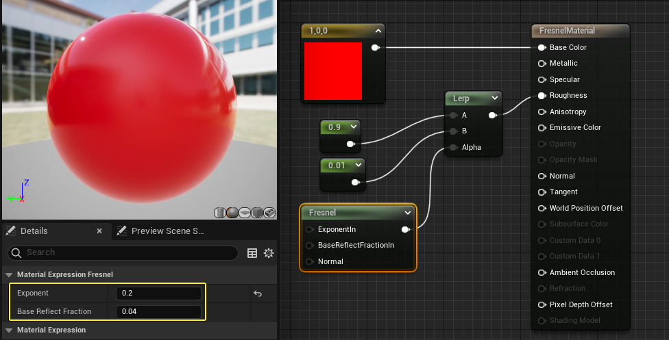
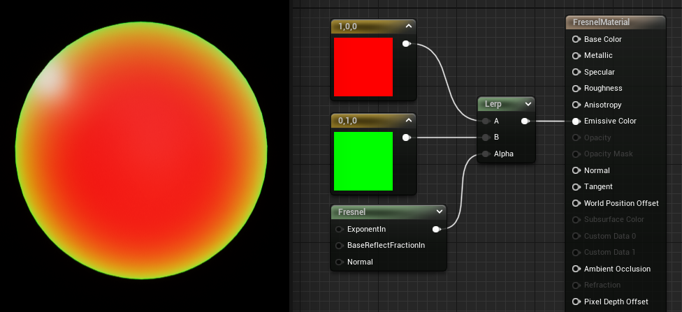
The Fresnel node is a versatile utility for alpha blending between two different inputs in a Lerp node.
In the image below the Fresnel node in the Alpha input controls the transition between the red and green colors in Input A and B on the Lerp.
By that same logic you could use Fresnel to control the placement of different Roughness values on your mesh. In the image below the Fresnel is used to transition between Roughness values of 0.1 at the edges and 0.9 toward the center of the sphere. This creates an illusion that the sphere is more reflective near the edges, similar to the way glass behaves.