When using the Clear Coat Shading Model, you can enable an option to use a second normal map for the surface beneath the clear coat layer. This option provides a more accurate model for complex Materials like carbon fiber, in which the underlying layer has different geometric surface properties than the clear coat layer. This tutorial covers how you can enable dual normals in the Clear Coat Shading Model and how to use this feature in your projects.
What the Second Normal Does
The comparison below shows what happens when a second normal map is added to a carbon fiber Material using the Clear Coat Shading Model.
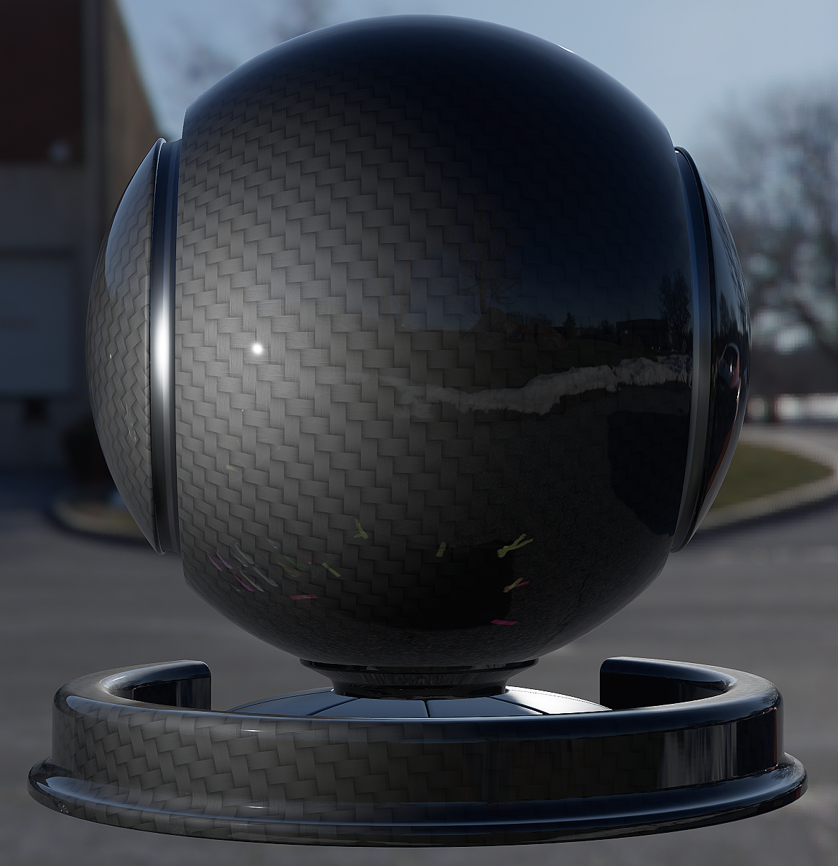

In the image on the left, Clear Coat Bottom Normal is turned off. While the surface under the Clear Coat is interacting with the lighting, the light is only affecting the surface in one direction. This makes the surface appear flat and smooth, which is inaccurate for carbon fiber which should have an alternating woven pattern.
In the image on the right, Clear Coat Bottom Normal is enabled. You will notice that the light is now interacting with the carbon fiber weave, producing an alternating pattern of highlights and shadows with a sense of directionality.
Required Files
To follow this tutorial, you will need to download, extract, and then import the following texture files into your Unreal Engine project. If you are unfamilar with how to do this, read the Texture Import Guide for more information.
Required Textures Download (Right-click and save link as.)
Enabling the Clear Coat Second Normal Option
To use two sets of normals in the Clear Coat Shading Model, you will need to enable the feature in the Project Settings.
-
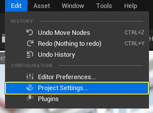
From the Main Toolbar go to Edit > Project Settings.
-
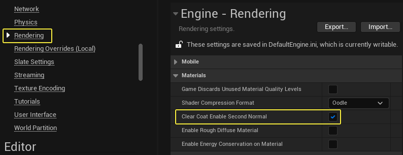
In the Project Settings window, go to Rendering > Materials and then check the box next to Clear Coat Enable Second Normal option to enable the feature.
-
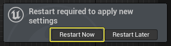
You must restart the Editor to finish enabling the feature. Click Restart Now in the dialog when prompted.
Using the Clear Coat Second Normal Option
Use the following steps to create a Clear Coat Material that uses a second normal map for the underlying layer.
-
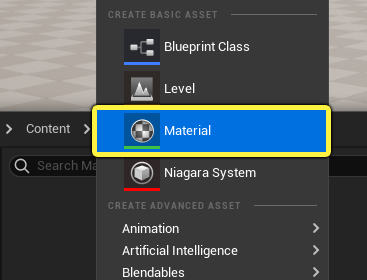
Right-click in the Content Browser and select Material in the Create Basic Asset section of the context menu.
-
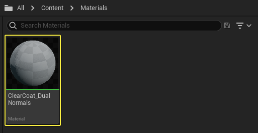
Give the Material asset a descriptive name like like ClearCoat_DualNormals. Double-click the Material to open it in the Material Editor.
-
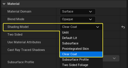
In the Material Editor, click anywhere in the Material Graph to display the Material Properties in the Details Panel. Change the Shading Model of the Material from Default Lit to Clear Coat.
-
Add four Scalar Parameter Expression nodes to the Material Graph. Give them the follwing names and Default Values, then connect them to the Main Material Node so they match the image below.
Material Expression Type Name Default Value Scalar Parameter Base Color 0.04 Scalar Parameter Metallic 1.0 Scalar Parameter Clear Coat 1.0 Scalar Parameter Clear Coat Roughness 0.1225 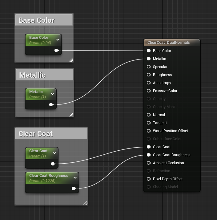
-
To setup the Roughness section of the Material, add the following Material Expressions to the graph. Change the name and default value of each Scalar Parameter so they match the table below. After renaming the parameters, connect all the Material Expressions so your graph matches the image beneath the table.
Material Expression Type Name Default Value Scalar Parameter Roughness Scaling 30.0 Scalar Parameter Roughness Min 0.1 Scalar Parameter Roughness Max 1.349 Texture Sample N/A T_CarbonFiber_R_00 Texture Coordinate N/A N/A Multiply N/A N/A Linear Interpolate N/A N/A 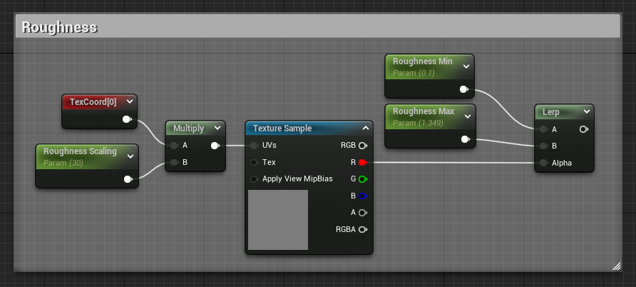
-
Since this Material uses two normal maps, you will need to create two different Normal map sections in the Material Graph. The first section will define the normals of the Clear Coat surface and will require the following Material Expression nodes. Rename the Scalar Parameters and set their Default Values according to the table. Connect the Material Expressions so they match the image below.
Material Expression Type Name Default Value Scalar Parameter Clear Coat Normal Strength 0.98 Scalar Parameter Clear Coat Normal Scaling 30.0 Texture Sample N/A T_CarPaint_N_00 Texture Coordinate N/A N/A Multiply N/A N/A FlattenNormal N/A N/A 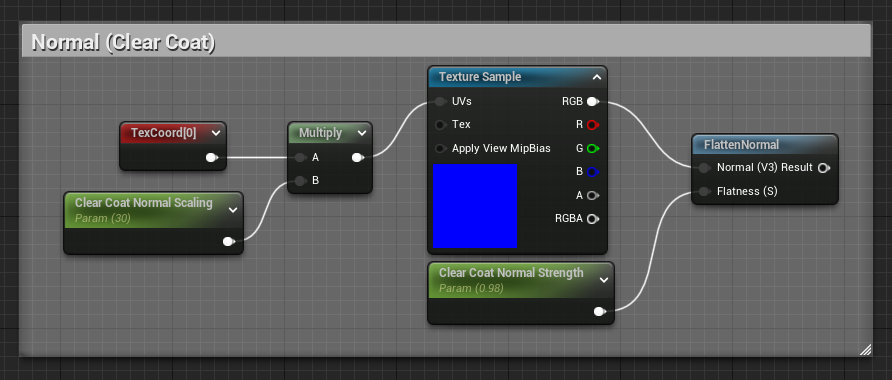
-
The second normal map will define the carbon fiber surface that is beneath the clear coat. Add the Material Expressions listed below, and give them the following names and default values. Connect the Material Expression nodes so that they match the image below.
Material Expression Type Name Default Value Scalar Parameter Carbon Fiber Scaling 30.0 Scalar Parameter Carbon Fiber Strength 0.5 Texture Sample N/A T_CarbonFiber_N_00 Texture Coordinate N/A N/A Multiply N/A N/A FlattenNormal N/A N/A ClearCoatBottomNormal (ClearCoatNormalCustomOutput) N/A N/A Click image for full size.
Make sure you have added the ClearCoatBottomNormal Material Expression node to the Material Graph and that you have connected the Normal map you want to use to its input. Failing to do this will result in you not being able to see the second Normal map in your Material.
-
With all the individual sections of the Material Graph now complete, connect the output of the Lerp in the Roughness section to the Roughness input on the Main Material Node. Connect the output of the FlattenNormal node to the Normal input on the Main Material Node. You do not need any additional connections for the carbon fiber normal map, because it is already connected to the ClearCoatBottomNormal custom output node. The final Material Graph is pictured below.
Click image for full size.
-
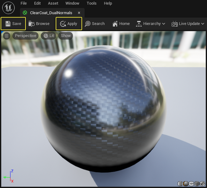
Click Apply and Save in the Material Editor toolbar to compile the Material and save the asset. The finished carbon fiber Material should look like the preview shown below.