
The ability to render realistic looking human skin is a must for any modern Video Game engine. To fulfill this need, Unreal Engine now offers a shading method specifically for skin or wax like surfaces called Subsurface Profile. While the Subsurface Profile shading model has similar properties to the Subsurface shading model, its key difference is in how it renders. SubsurfaceProfile uses a rendering approach that is based in Screen Space because this helps to better display the subtle subsurface effects seen in human skin where backscattering is a secondary effect only seen in few cases like ears for example. The following document will cover what a Subsurface Profile is and how you can use them in your work.
Enabling Materials to use Subsurface Profiles
Enabling your Material to use a Subsurface Profile can be done in the following few steps.
-
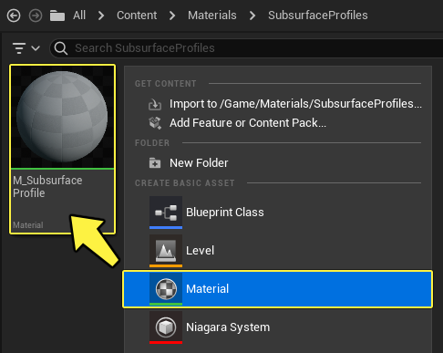
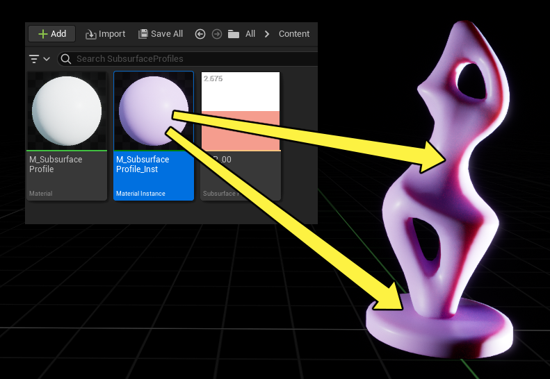
First create a new Material by Right-Clicking in the Content Browser and then selecting Material from the Create Basic Asset list. Once created, make sure that you name the Material. For this example, the Material will be named M_Subsurface_Profile. When completed, your Content Browser should look like this.
-
Double-click the Material in the Content Browser to open it in the Material Editor.
-
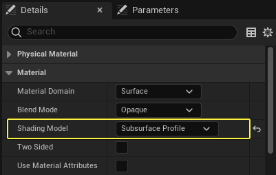
Now with the Material open, we need to change the Material's Shading Model from Default Lit to Subsurface Profile in the Details panel.
-
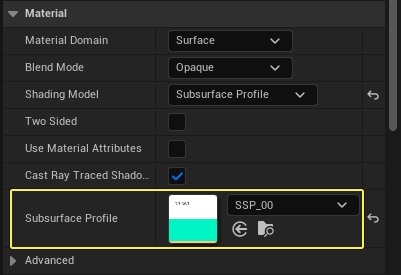
At this time, you can assign a Subsurface Profile by inputting one into the Subsurface Profile section in the Details panel.
-
Now the Material is ready to be used with a Subsurface Profile.
Creating Subsurface Profiles
Creating Subsurface Profiles is something that can be accomplished in the following steps.
-
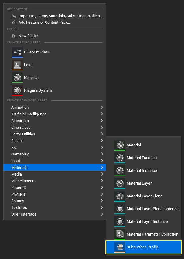
First Right-Click in the Content Browser, open the Materials context menu, and select the Subsurface Profile option.
-
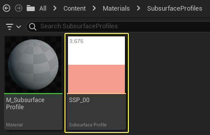
Once the Subsurface Profile has been selected and created, you can name it. For this example, we will name our Subsurface Profile SSP_00. Once completed, you should have something that looks like this.
Creating a Material that Uses a Subsurface Profile
Now that the Material and Subsurface Profile have been created, it is now time to fill them in with data. In the following steps, we will be creating a Material and a Material Instance that can make use of a Subsurface Profile.
-
Open the M_Subsurface_Profile Material in the Material Editor if you do not already have it opened.
- With the Material open, it is time to place down some Material Expression nodes. For this tutorial, we are going to make use of the following nodes.
- Vector Parameter x 1
- Scalar Parameter x 2
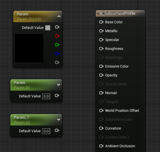
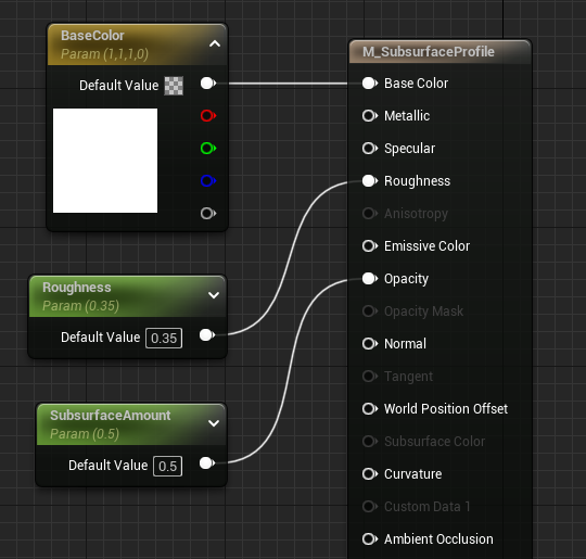
- Now that we have the Material Expression parameter nodes added to the graph, you will need to name them and fill in their default values. For this example, we will be giving the nodes the following names and default values.
| Property Name | Value |
|---|---|
| BaseColor | R: 1.0 G: 1.0 B: 1.0 |
| Roughness | 0.35 |
| SubsurfaceAmount | 0.5 |
Connect each of the nodes to their corresponding input on the Main Material Node. When everything has been filled in, your shader graph should look something like this.
-
Now that everything is wired up, you can add your Subsurface Profile to the Material. To do this, first find the Subsurface Profile input in the Material section of the Details panel. Use the drop-down menu to select the SSP_00 asset you created earlier, or drag it from the Content Browser directly onto the input.
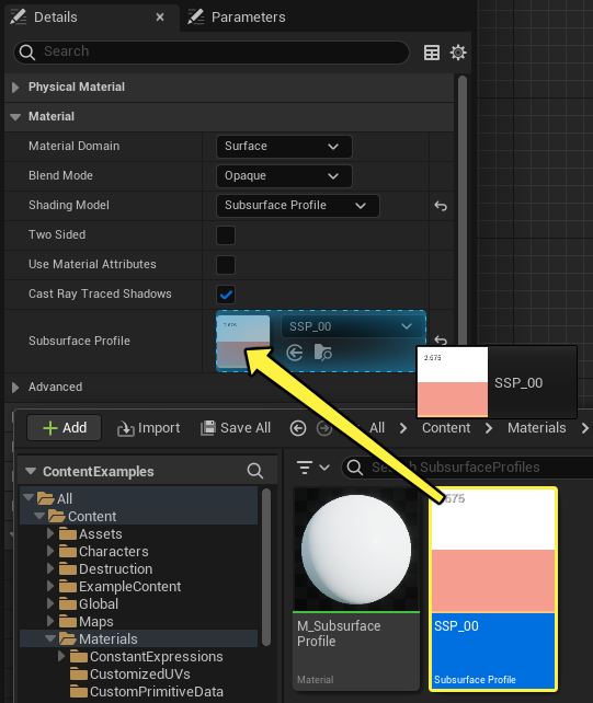
If you do not provide a Subsurface profile, a default one will be used. The default one that is used is a close approximation to Caucasian skin.
-
With the Subsurface Profile applied and the Material expressions linked to the main Material node, it is now time to compile the shader and get ready to make a Material Instance out of this Material. When completed with the Material, it should look something like this.
Using a Subsurface Profile in a Material Instance
-
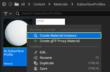
With the Material now created and compiled, it is now time to make some Material Instances to make tweaking of parameters faster. To make a Material Instance from our Material, first locate the Material in the Content Browser and then Right-Click on it and select the Create Material Instance option. When completed, your Content Browser should look something like this.
-
Now that the Material Instance has been created, open it up by using the Left Mouse Button to Double-Click on it in the Content Browser. Once open, you should see something that looks like this.
-
To change the Subsurface Profile in a Material Instance, you can enable the Subsurface Profile override by checking the box, and then use the drop-down menu to select a different Subsurface Profile asset. Once you click on the input you should see the Subsurface Profiles that are available to choose from.
If you have already supplied a Subsurface Profile in the Parent Material, then you do not need to override it in the Material Instance. This is only if you wish you use a different Subsurface Profile than what is already being used.
Applying a Subsurface Profile Material
-
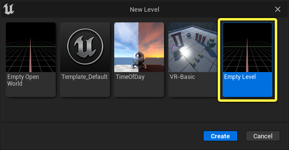
Now that the Material Instance has been created, it is now time to test out our new Material. To do this, we first need to create a new blank level to work in by going to the main menu and under the File option select New Level. When prompted what type of level to select, select the Empty Level.
-
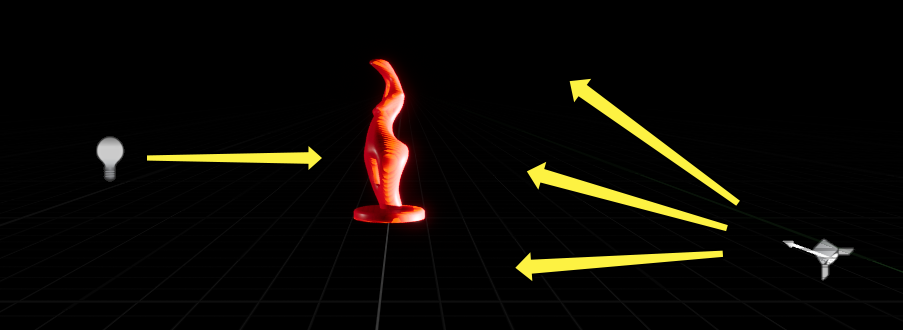
To test the Material, we will use a Static Mesh from the Starter Content, lit from the front by a Point Light, and from behind with a very bright Spot Light. This strong backlighting will help demonstrate how Subsurface Profile Materials can transmit and scatter light. The lighting configuration should look something like the image below.
-
Find the SM_Statue Asset in the Content Browser under StarterContent > Props and add it to your Level. The location and rotation settings in our example are shown below.
Property Name Value Location: X:0, Y: 0, Z:0 Rotation: X:0, Y: 0, Z:-23 -
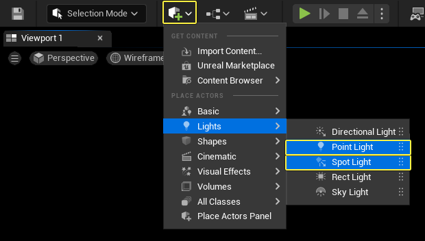
Open the Place Actors menu and add both a Point Light and a Spot Light to your level.
-
Select the Point light and configure it with the following settings in the Details Panel.
Property Name Value Location: X:380, Y: 0, Z:80 Intensity: 8.0 cd 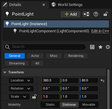
-
Select the Spot Light and configure it with the following settings in the Details Panel.
Property Name Value Location: X:-650, Y: 100, Z:-75 Rotation: X:0, Y:20, Z:0 Intensity: 1500 cd 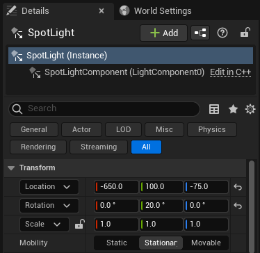
-
Apply the M_Subsurface_Profile_Inst Material instance to the statue by dragging it from the Content Browser onto the Static Mesh in the Level, or onto both of the statue's Material Elements in the Details panel. Make sure you drag it onto both pieces of the sculpture.
-
The effect of the Subsurface Profile is most obvious along the edges of the highlight, where the spotlight falls into shadow. Along this contour, you can see the reddish-pink subsurface color coming through, in contrast to the lavender base color of the statue and the intense white highlight.
Adjusting a Subsurface Profile
-
Once the Material Instance has been applied to the statue, you can adjust the Subsurface Profile settings. To do this, open the Subsurface Profile by double-clicking the SSP_00 asset in the Content Browser. You should see something like this being displayed.
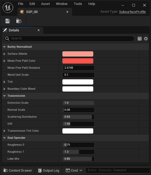
You can adjust the properties of the Subsurface Profile by changing the values or colors in the editor.
-
Surface Albedo: Should match the base color of the corresponding Parent Material as closely as possible.
-
Mean Free Path Color: Controls how far light penetrates into the surface for the red, green, and blue channels, and determines the color of the region where light is scattered beneath the surface. Lighter values allow more transmission, black effectively turns off the subsurface scattering.
-
Mean Free Path Distance: A distance in world/Unreal units (cm), which scales how far light will penetrate into the surface. Decreasing makes the subsurface region tighter/sharper, increasing this value makes the subsurface region larger and blurrier.
-
-
Keep in mind that you can adjust the parameters of the Subsurface Profile in real time as demonstrated below.
Tips & Tricks
Because of how Subsurface Profiles render, there are a few Tips & Tricks to getting the most out of using them.
Scatter Radius
Setting the Mean Free Path Distance of the Subsurface profile to a really big number will result in rendering errors as you can see in the following image.
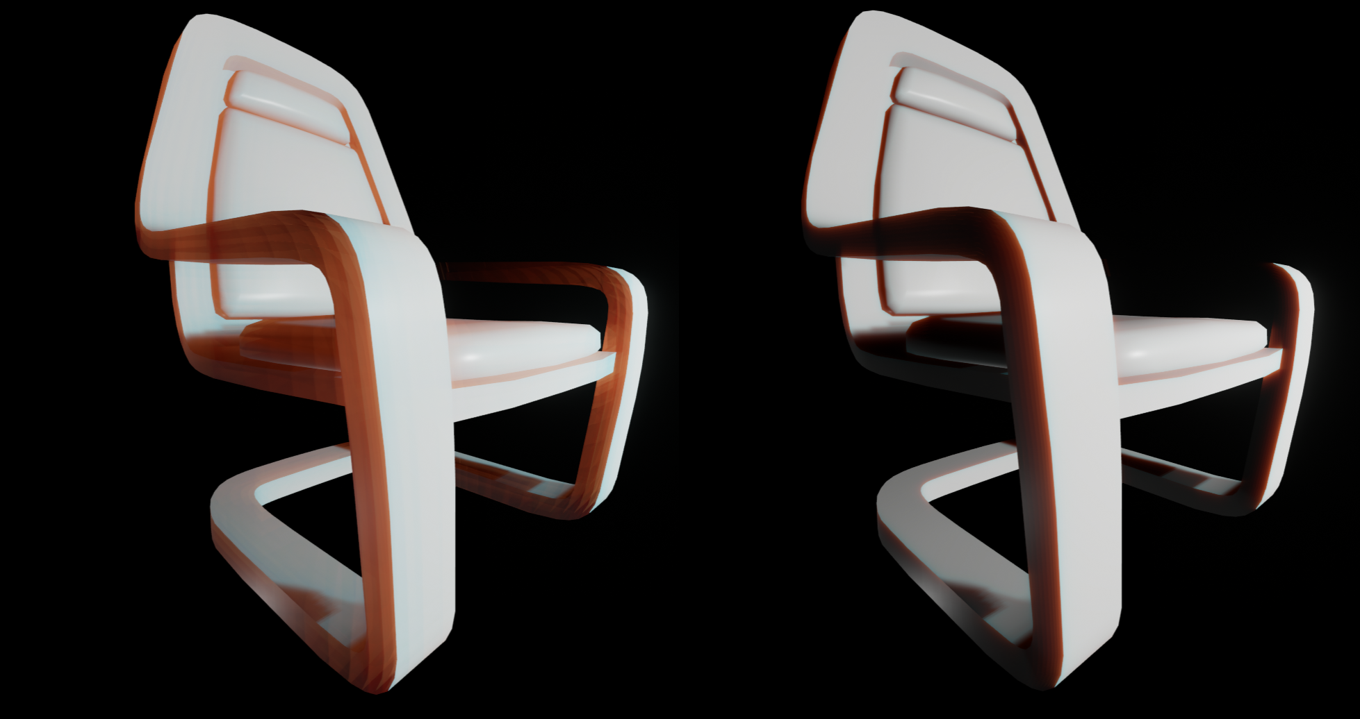
In the image on the Left, the Mean Free Path Distance was set to 50. Notice how it looks like there are multiple images rendered on the surface. Now take a look at the image on the Right. In this image the Mean Free Path Distance was set to 5.0. Notice how the image looks softer and more natural. This is the type of effect we are trying to achieve.
Combining a Material Instance with a Subsurface Profile
Combining a Material Instance with a Subsurface profile is a great way to get the most control over your results for a number of reasons.
- A Material Instance allows you to tweak values in real time which makes seeing your results much quicker.
- You can use the Opacity input to dampen the Subsurface contribution to the surface. However it is recommended that you keep this value at 1 and adjust the parameters inside the Subsurface Profile. Only adjust this value if you find that you cannot get the results you are looking for when adjusting the Subsurface Profile.
- The Value slider of each color picker controls the influence of the Subsurface effect. The closer that this value is set toward white, the more prominent the effect will be. While the closer the value is set to black, the less visible the effect will be.