
You define most aspects of the nDisplay system through a single configuration asset, the nDisplay Config Asset, through the nDisplay 3D Config Editor. This asset defines the computers that make up your cluster network, the characteristics of the windows and viewports you want the Unreal Engine to render on each computer, the display device's topology and configuration, the parts of the virtual world each viewport should render, the types of input devices you want to accept, and more.
This page describes all the settings available in the nDisplay 3D Config Editor.
Click image to enlarge
-
Toolbar, located in the top left of the Editor.
-
Components, located on the left below the Toolbar.
-
Preview, located in the middle of the Editor to the right of the Components panel.
-
Details, located on the right of the Editor next to the Preview panel.
-
Cluster, located on the left of the Editor below the Components panel.
-
Output Mapping, located in the middle of the Editor below the Preview panel.
-
Compiler Results, located in the bottom right of the Editor below the Details panel.
Toolbar

The Toolbar in the 3D Config Editor shares most of the buttons with the Toolbar in the Blueprint Editor. The following are the two buttons unique to the nDisplay 3D Config Editor:
-
Import: Imports an nDisplay configuration file (
.ndisplay,.cfg) from the local computer. -
Export: Exports the nDisplay settings to a configuration file (
.ndisplay) on the local computer.
Refer to Toolbar for more details on the other options.
Components
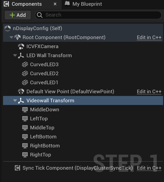
The Components panel defines the physical display, tracking, and in-camera setup for the nDisplay cluster. Adding components to the inherited Root Component is the first step in designing an nDisplay network. You can pick from a predefined list of Displays, Transforms, and default Camera Actors, or add any available UE components.
To use nDisplay with real-world tracking systems, add a Live Link Component to the Components panel. Refer to Live Link for more on how to configure this for your setup.
The following sections describe the nDisplay-specific components that can be added to your setup.
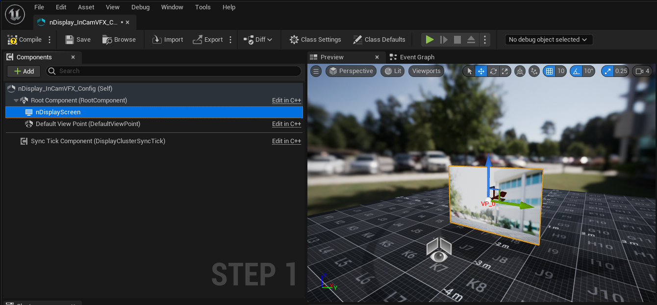
Screen
nDisplay Screen Components are meant to conveniently define flat 2D displays of any size, shape, and resolution. With the referenced view point, the View Origin Component, they define a volume, called the view frustum, that renders a portion of your 3D scene from the camera's or the view point's perspective. The rendered pixels are stored in the Viewport structure, which binds a display, a view point, and a projection policy together. Each of these projection screens need to have the same or similar dimensions in space as the physical screen that you'll use to render it. This setup is compatible with most projection policies.
The pivot point of a screen is always in its exact midpoint.
Static Mesh
When dealing with non-flat displays such as curved LED walls or displays, you can use the Static Mesh Component instead of the Screen Component. This allows you to fully define the shape of your screen using a Static Mesh. This setup is compatible with most projection policies.
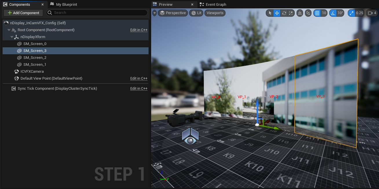
Xform
By default, the parent of all objects is the Root Component origin: an arbitrary point in 3D world space where the X, Y, and Z axes have their zero point. You can also configure specific named transforms in 3D space, called Xforms, which can act as parents for one or more components. This can help simplify the spatial layout of your screens, cameras, and other components. Xforms include a visualization mesh and the ability to scale the component in the Details panel.
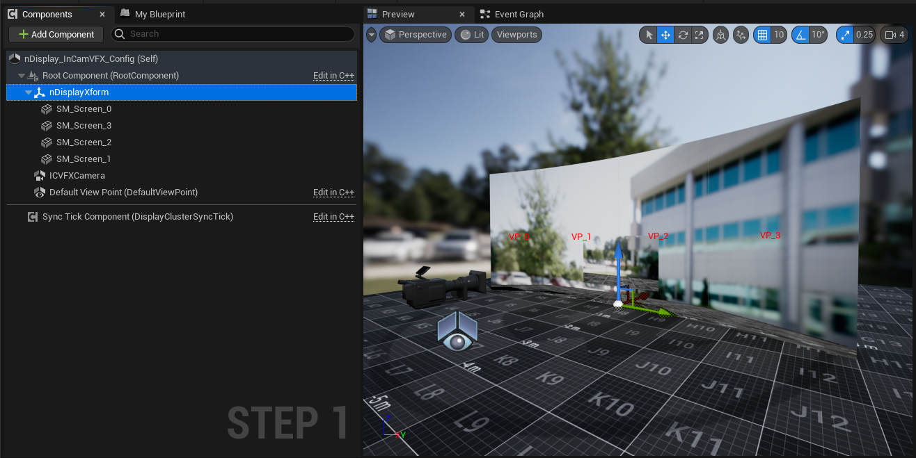
You can use UE's standard Scene Components instead of Xforms to act as a parent for one or more components, but they will not have the visualization mesh or the ability to control their size in the Details panel.
View Origin
The component for the nDisplay setup that defines the origin for what's rendered in the viewports. Alongside screens or static mesh components defining your displays, they define a view frustum used for rendering 3D content properly. You can have multiple View Origins in your configuration file and bind them to different viewports and displays. The View Origin also contains the settings for Stereo Rendering with nDisplay.
ICVFX Camera
This is a Cine Camera Component where you can reference or link to an external camera placed within your level or project. This component creates the inner frustum necessary for in-camera VFX projects.
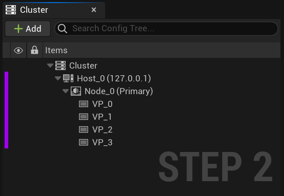
Cluster
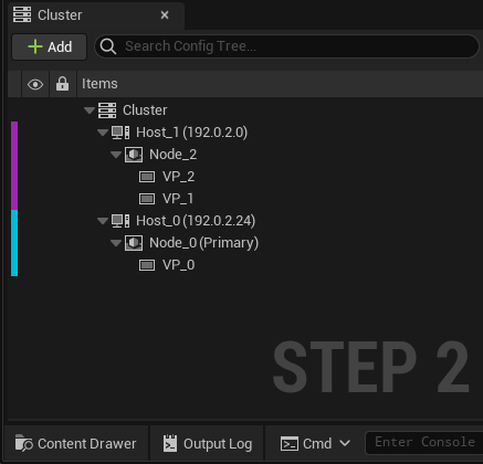
For each different instance of your Unreal Engine application that you'll use in your nDisplay network, you need to define a Cluster Node. Each Cluster Node is a representation of an application instance, and defines the hostname or IP address of the computer that will run that application instance. You may set up a different physical computer for each Cluster Node, or you may have multiple Cluster Nodes that run on the same host.
Each Cluster Node contains one or more Viewports. Alongside their associated display or static mesh components, they define the window in the 3D world. This window is then used to render your scene from the perspective of any View Origin. The following table describes the elements that can be added to the Cluster.
| Nodes | Description |
|---|---|
| Cluster | Hosts a group of PCs forming one nDisplay cluster. Only one can be created per nDisplay Config Asset. |
| Host | Representation of a PC with a unique IP address. Customize the color signature to differentiate one PC from another. The color is also used in the Output Mapping panel. |
| Node (Application Instance) | An instance of UE. Typically there is one application instance per PC but more is allowed for specific use cases. The application instance window is configured in the Details panel for this node. |
| Viewports | Defines a window in the 3D world. Container for the Projection Policies, Cameras, and target Displays. |
Cluster Configurations
To access the Cluster settings:
-
Select Cluster in the Cluster panel to open its Details panel.
-
In the Details panel, expand the Configuration section.
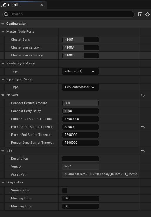
In the Cluster settings, you can set the ports, network, and sync policies for the cluster. For more details on changing the Port, Network, and Synchronization settings, see Changing nDisplay Communication Ports and Synchronization in nDisplay.
Output Mapping
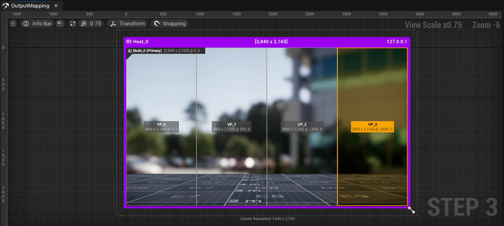
The Output Mapping panel effectively maps Viewports defined in the Cluster panel to the 2D UE application windows. In the Output Mapping panel, you can:
-
View the relationship between the host computer, the Cluster Node (UE application instance), and the viewport.
-
Visualize, edit, and map 2D viewports inside an application instance window.
-
Translate and rotate viewports.
Use the following tools, located in the top left corner of the Output Mapping panel in left to right order, to modify the windows and viewports for your nDisplay cluster:

| Button | Shortcut | Description |
|---|---|---|
| Hamburger Menu | You can enable or disable the following options:
|
|
| Info Bar | W | Enabling this option shows window information, such as the resolution and IP address. |
| Show Viewports Outside Window | R | Enabling this option shows any viewports that are outside the application window. |
| Zoom to Fit | Z | Automatically zoom to fit the panel view. |
| View Scale | Set the scale for the windows and viewports. | |
| Transform Operations | Options to apply transformations to a viewport::
|
|
| Positioning Settings | Settings for how nodes are positioned. You can enable or disable the following options:
|
|
| Node Snapping | Options for how nodes snap together. You can enable or disable the following options:
|
Window Configurations
Each window configuration defines a set of properties for the main window of an instance of your Unreal Engine application. You use it to configure details like the starting size and placement of the window when nDisplay launches your application, and whether or not the window should take up the full screen.
You also provide one or more viewport configurations, which identify specific areas within the main application window that nDisplay will fill with renderings of your scene.
In the nDisplay 3D Config Editor, you can configure the window by selecting the Cluster Node in the Output Mapping panel and modifying its size, or changing the settings in the Window section of the Cluster Node's Details panel.
Output Remapping
With Output Remapping, you can specify how Viewports are rendered in terms of position and scale within the Application Window. Output Remapping extends this functionality by allowing custom transforms such as rotation that are defined in the provided mesh's UV channel.
For example, you can translate, rotate, and scale parts of the output image so that they appear in different regions of the application window.
Click image to enlarge
There are three ways to enable this feature:
-
Assigning a Static Mesh which contains a planar geometry with a custom UV mapping.
-
Assigning an external .obj file that contains a planar geometry with a custom UV mapping.
-
Select a viewport in the Output Mapping panel and choose a Transform Operation.
Output Remapping with a Static Mesh or External File
To apply output remapping, you can provide either a Static Mesh or an external .obj file that contains a planar geometry with a custom UV mapping set up. nDisplay will use the UV channel set for your plane to determine how the output image is mapped to each part of the application window.
The input mesh can be of unit size and will be applied to the whole application window. This is because nDisplay uses the final render buffer as an input GPU Texture Sampler to a final post process shader applied to the mesh with an arbitrary UV space.
Click image to enlarge
When you apply rotation to the nDisplay render with an external file, you must manually resize the Application Window resolution to accommodate for the rotation, otherwise the render will appear stretched.
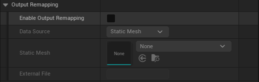
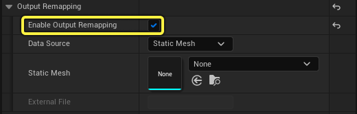
To enable Output Remap in your Project:
-
In the Cluster panel, select a Node to open its Details panel.
-
In the Details panel, expand the Output Remapping section.
-
Enable Output Remapping.
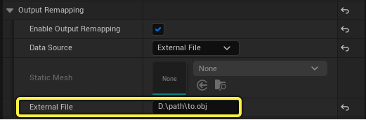
-
Choose which Data Source you want to use: Static Mesh or External File.
- For Static Meshes: Browse to a Static Mesh in your project.
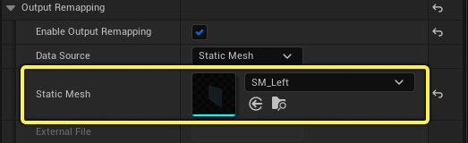
- For External Files: Enter the path on disk to an .obj file.
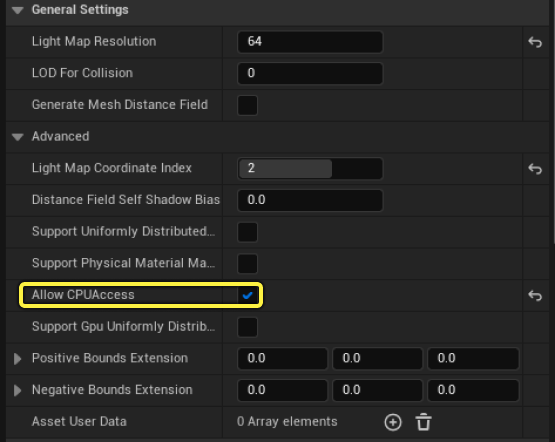
In order to use a Static Mesh with Output Remapping, Allow CPUAccess must be enabled for the Static Mesh. To do this:
-
Double-click the Static Mesh in the Content Browser to open it in the Static Mesh Editor.
-
In the Details panel, expand General Settings > Advanced.
-
Enable Allow CPUAccess.
-
Save the Static Mesh Asset to keep your changes.
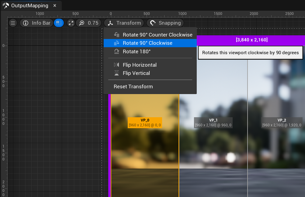
Output Remapping with Transform Operations
You can transform viewports within the Output Mapping panel to modify how they'll be rendered within the application window.
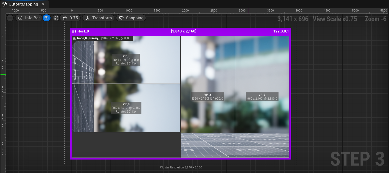
The left two viewports were rotated 90 degrees clockwise and scaled down to fit the space.
To quickly apply either a rotation or flip transform to a viewport in your project:
-
Select the viewport either in the Cluster panel or in the Output Mapping panel.
-
In the Output Mapping panel, select Transform and choose the operation you want to apply.
Alternatively, right-click on a viewport to open the contextual menu and select the desired Transform.
Viewport Configurations
Each window configuration refers to one or more viewport configurations, each of which defines a rectangular area of the window that nDisplay should fill with a rendered view of the scene. Usually, a viewport starts at the upper left corner of the application window, and its width and height are set so that they fill the parent window.
In some cases you may need to offset, scale, or rotate the viewport within its parent application window. For example, LED processors sometimes have custom 2D mapping programmed within a larger canvas. With the nDisplay Output Mapping panel you can place or rotate your viewports so they fit within the region expected by the display devices or processors. You can load a custom background image per application window to help with viewport placements.
If you rotate or translate your displays with the OS configuration, you can use the Output Mapping tools to match that arbitrary rotation and location as well.
Each viewport configuration described above refers to a projection policy, which is responsible for defining how the image is rendered within the viewport. Unreal automatically attaches the whole cluster to the current camera's position so that baked or interactive camera animations are made possible. You can disable the camera for your needs.
In most common 2D situations, you will use the Simple projection type, which renders the virtual world with a view frustum defined by the display configuration and the View Origin. Those rendered pixels are effectively stored and defined by the attached viewport.
More complex setups, such as for in-camera VFX or when the displays are curved or an arbitrary shaped surface, you can use the Mesh or MPCDI projection policies.
Other industry-specific projection types, such as EasyBlend, VIOSO, and DomeProjection, are targeting display surfaces lit by projectors and use other methods to define or adapt the rendered content for the viewport. They may introduce additional corrections or apply custom rendering techniques before rendering the image to the rectangular viewport. For example, the projection may squash, stretch, or distort the image so that it will look natural when displayed on a curved or an arbitrary shaped surface. They can also apply required color or gamma curve corrections for a continuous rendered image.
For more details on projection types and their configurations, see Projection Policies in nDisplay.
Texture Share
With TextureShare, you can share the viewport texture with another application, or receive a texture from another application and display it in the specified viewport.
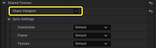
To enable texture sharing for a viewport:
-
In the 3D Config Editor, select the viewport to view its Details panel.
-
In the Details panel, enable Share Viewport.
-
You can now use the viewport in your external application to send or receive a texture.
Refer toTexture Share for more details on the sync settings and how to set up your external application.
3D Viewport
With the 3D Viewport, you can visualize the display, camera, and tracking setup of your nDisplay cluster. This panel is a 3D editing tool that provides the means for you to visualize and edit the following:
-
Display topology and projection policies.
-
The tracked camera location.
-
The tracked user location.
Use this view to ensure:
-
Your displays are properly set up.
-
The preview render looks correct from the camera vantage point.
-
Viewports are properly mapped to the screens.