MetaSound Function nodes come in many types and provide the functionality required to play audio files, mix sounds, apply filters and effects, and more. This document contains a list of function nodes with detailed information on each.
For more detailed information on the features available in MetaSounds, see MetaSounds Reference Guide.
General
BPM To Seconds

The BPM To Seconds node calculates a beat time in seconds from the given beats per minute (BPM), beat multiplier, and divisions of a whole note.
| Input |
Description |
| BPM |
The input target BPM. |
| Beat Multiplier |
The multiplier value to apply to the BPM. |
| Division of Whole Note |
The divisions of a whole note. |
BPM To Seconds Outputs
| Output |
Description |
| Seconds |
The output beat time in seconds. |
Envelope Follower

The Envelope Follower node outputs an envelope from an input audio signal.
| Input |
Description |
| In |
The input audio signal. |
| Attack Time |
The attack time (in seconds). |
| Release Time |
The release time (in seconds). |
| Peak Mode |
The following-method of the envelope follower:
- MS: Envelope follows a running Mean Squared of the audio signal.
- RMS: Envelope follows a running Root Meat Squared of the audio signal.
- Peak: Envelope follows the peaks in the audio signal.
|
Envelope Follower Outputs
| Output |
Description |
| Envelope |
The output envelope value (block rate). |
| Audio Envelope |
The output envelope value (audio rate). |
Flanger

The Flanger node applies a flanger effect to the input audio.
| Input |
Description |
| In Audio |
The input audio signal to apply the flanger effect to. |
| Modulation Rate |
The Low-Frequency Oscillator (LFO) rate that varies the delay time (in Hz). This value is clamped at block rate. |
| Modulation Depth |
The LFO amplitude (strength) that scales the delay time. |
| Center Delay |
The center delay amount (in milliseconds). |
| Mix Level |
The balance between original and delayed signal. The value should be between 0 and 1.0. For example, a value of 0.5 uses equal amounts of each signal and a value greater than 0.5 uses more delayed signal than non-delayed signal. |
Flanger Outputs
| Output |
Description |
| Out Audio |
The output audio signal with the flanger effect applied. |
Get Wave Duration

The Get Wave Duration node returns the duration of an input Sound Wave asset (in seconds).
| Input |
Description |
| Wave |
The Sound Wave asset to get the duration of (in seconds). |
Get Wave Duration Outputs
| Output |
Description |
| Duration |
The duration of the Sound Wave asset (in seconds). |
Get WaveTable From Bank

The Get WaveTable From Bank node retrieves (or generates an interpolated) WaveTable from a given WaveTable Bank asset.
| Input |
Description |
| WaveTableBank |
The WaveTable Bank asset to retrieve or generate an interpolated WaveTable from. |
| TableIndex |
The index of the WaveTable to retrieve. If set between two whole values, the WaveTables located at the two closest indices are mixed together. The value will be adjusted to loop if it is set beyond the range of the WaveTable Bank. For example, if the WaveTable Bank has 3 indices, a value of 3.0 will retrieve the WaveTable at index 0. |
Get WaveTable From Bank Outputs
| Output |
Description |
| Out |
The retrieved WaveTable. |
InterpTo

The InterpTo node interpolates between the current value and a target value over a specified time.
| Input |
Description |
| Interp Time |
The time to interpolate from the current value to the target value. |
| Target |
The value to interpolate to. |
InterpTo Outputs
| Output |
Description |
| Value |
The current value. |
RingMod
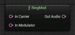
The RingMod node performs ring modulation with a carrier signal and a modulator signal.
| Input |
Description |
| In Carrier |
The carrier audio signal. |
| In Modulator |
The modulator audio signal. |
RingMod Outputs
| Output |
Description |
| Out Audio |
The modulated audio signal. |
Wave Player

The Wave Player node is used to play a Sound Wave asset. There are multiple versions of this node in order to support several different channel configurations, such as Mono, Stereo, Quad (4.0), 5.1, and 7.1.
| Input |
Description |
| Play / Stop |
The Play and Stop triggers start and stop the Wave Player playback at a sample-accurate moment in time. |
| Wave Asset |
The Sound Wave asset played by the Wave Player during playback. This asset uses the same real-time decoders as all other sound sources in Unreal Engine. |
| Start Time |
The time within the Sound Wave asset to begin playing the audio file. This is also referred to as seek time. |
| Pitch Shift |
The Pitch Shift to use for the Wave Player. This is defined in units of semitones to account for the non-linear nature of frequency scaling. |
| Loop |
Whether the Wave Player will loop the audio file or stop when it's finished. This can be toggled at any time during playback from the graph. |
| Loop Start |
The Loop Start indicates at which point in time the Wave Player will loop the audio file. |
| Loop Duration |
The Loop Duration represents the total time the loop will play. Any value other than -1 sets the end point of the loop to the sum of the Loop Start and Loop Duration values, while a value of -1 loops the entire audio file. |
Wave Player Outputs
| Output |
Description |
| On Play |
Triggers when the Wave Player's Input Play pin is triggered. |
| On Finished |
Triggers when the Wave Player finishes playing the audio file. This pin will trigger on the same sample point where the audio file finishes playing. |
| On Nearly Finished |
Triggers on the audio rendering block before the audio file is expected to finish playback. This is commonly used to loop back and pick a new audio file variation for the Wave Player. |
| On Looped |
Triggers on the sample where a sound looped based on the looping settings. |
| On Cue Point |
Triggers when a cue point has been parsed in the Wave Player. Cue points are metadata embedded in audio wave files on import.
Cue points are often used by sound designers to trigger events or loop points in their audio at exact points in time. With this feature, sound designers can procedurally trigger MetaSound behavior based on embedded data in the imported audio wave file.
This pin is executed with sample accuracy, but the integer and label associated with the cue point is read at the block rate. Cue points in the audio wave file that are closer together than the block rate of the MetaSound will only trigger on the last cue point in that block.
|
| Cue Point ID |
The ID of the cue point as parsed from the imported audio wave file. |
| Cue Point Label |
The label of the cue point as parsed from the imported audio wave file. |
| Loop Percent |
The current location in the audio wave file within the given loop region. |
| Playback Location |
The current location in the audio wave file as a fraction of the total length of the audio wave file. |
| Out X |
The X channel output of the input Sound Wave asset. |
In the case of mono file playback, the audio in the right and left channels are up-mixed using mono-channel duplication.
WaveShaper

The WaveShaper node applies a non-linear shaping to the input audio signal.
| Input |
Description |
| In |
The input audio signal to apply the non-linear shaping to. |
| Amount |
The amount of the non-linear wave shaping to apply. |
| Bias |
The DC offset to apply before wave shaping. |
| OutputGain |
The amount of gain to apply after processing. |
| Type |
The type of algorithm to use to process the audio: Sine, Inverse Tangent, Hyperbolic Tangent, Cubic Polynomial, or Hard Clip |
WaveShaper Outputs
| Output |
Description |
| Out |
The output audio signal with the non-linear shaping applied. |
Array
Array functions provide options to manipulate arrays within a MetaSound. Each of these functions have different versions which allows them to support arrays of several common data types, including: Bool, Float, Int32, String, Time, Transmission:Address, AudioBusAsset, WaveTableBankAsset, and WaveAsset.
Concatenate

The Concatenate node concatenates two arrays on a given trigger.
| Input |
Description |
| Trigger |
The trigger on which to concatenate the input arrays. |
| Left / Right Array |
The input arrays. |
Concatenate Outputs
| Output |
Description |
| Array |
The concatenated array. |
Get

The Get node retrieves an element from an array at the given index.
| Input |
Description |
| Trigger |
The trigger on which to retrieve the specified array element. |
| Array |
The array from which to retrieve an element. |
| Index |
The index of the element to retrieve. |
Get Outputs
| Output |
Description |
| Element |
The value of the retrieved element. |
Num

The Num node returns the number of elements in the given array.
| Input |
Description |
| Array |
The array whose elements will be counted. |
Num Outputs
| Output |
Description |
| Num |
The number of elements in the given array. |
Random Get

The Random Get node randomly retrieves elements from an input array. Optionally, an array of weights can be supplied to adjust the randomness.
| Input |
Description |
| Next |
The trigger on which to get the next random value in the array. |
| Reset |
The trigger on which to reset the randomization seed for the array. |
| In Array |
The input array from which to randomly retrieve elements. |
| Weights |
(Optional) An input array of weights used to define the probability of each entry retrieved. If not provided, an even probability for all elements is assumed. If this array is shorter than the input array, it is repeated to match the size. |
| Seed |
The seed used for the random shuffle. The default value of -1 will use the current time. |
| No Repeats |
The number of elements to track to avoid repeating in a row. For example, a value of 2 prevents this node from repeating the last two selected elements. |
| Enabled Shared State |
If enabled, this node's state is shared across instances of this MetaSound to avoid playing the same exact variations at the same time. |
Random Get Outputs
| Output |
Description |
| On Next |
Triggers when the Next input is triggered. |
| On Reset |
Triggers when the Shuffle input is triggered or if the array is auto-shuffled. |
| Value |
The randomly-selected value from the input array. |
Set

The Set node sets the value of a specified index in a given array.
| Input |
Description |
| Trigger |
The trigger on which to set value in the array. |
| Array |
The array in which a value will be set. |
| Index |
The index to set in the target array. |
| Value |
The value to which the selected index is set. |
Set Outputs
| Output |
Description |
| Array |
The array after the setting operation is completed. |
Shuffle

The Shuffle node outputs elements from a shuffled array.
| Input |
Description |
| Next |
The trigger on which to get the next value in the shuffled array. |
| Shuffle |
The trigger on which to shuffle the array manually. |
| Reset Seed |
The trigger on which to reset the random seed stream. |
| In Array |
The array from which to shuffle and output elements. |
| Seed |
The seed used for the random shuffle. The default value of -1 uses the current time. |
| Auto Shuffle |
If enabled, automatically shuffles when the array has been read completely. |
| Enabled Shared State |
If enabled, the state is shared across instances of this MetaSound. |
Shuffle Outputs
| Output |
Description |
| On Next |
Triggers when the Next input is triggered. |
| On Shuffle |
Triggers when the Shuffle input is triggered or if the array is auto-shuffled. |
| On Reset Seed |
Triggers when the Reset Seed input is triggered. |
| Value |
The value of the currently-selected element. |
Subset

The Subset node returns a subset of an input array.
| Input |
Description |
| Trigger |
The trigger on which to generate a subset. |
| Array |
The input array from which to get a subset. |
| Start / End Index |
The first and last indices to include in the subset. |
Subset Outputs
| Output |
Description |
| Array |
The subset of the input array. |
Debug
Print Log

The Print Log node is used to record values to the Output Log on a given trigger for debugging purposes. There are multiple versions of this node in order to support several common data types, including: Bool, Float, Int32, and String.
| Input |
Description |
| Trigger |
The trigger on which to write the set value to the log. |
| Label |
The label to attach to the value logged. |
| Value To Log |
The value to record to the log when triggered. |
Delays
Delay

The Delay node provides a mono buffer delay that supports dry level, wet level, and feedback. For multi-channel buffer delay, use the Stereo Delay node.
| Input |
Description |
| In |
The audio signal to apply delay to. |
| Delay Time |
The amount of time to delay the audio (in seconds). |
| Dry Level |
The level for the unprocessed (dry) signal |
| Wet Level |
The level for the processed (wet) signal. |
| Feedback |
The amount of feedback to use. |
| Max Delay Time |
The amount of feedback to use. |
Delay Outputs
| Output |
Description |
| Out |
The delayed audio signal. |
Delay Pitch Shift

The Delay Pitch Shift node pitch shifts the audio buffer using a delay-based doppler-shift method. This allows for pitch shifting without changing the length of the audio file by using an internal delay buffer. The pitch will shift but the sound will not speed up or slow down.
| Input |
Description |
| In |
The audio buffer to process. |
| Pitch Shift |
The amount of pitch shift (in semitones) to apply. |
| Delay Length |
The amount of delay (between 10 and 100 milliseconds) to apply. Changing this value can reduce artifacts in certain pitch shift regions. |
Delay Pitch Shift Outputs
| Output |
Description |
| Out |
The processed audio buffer. |
Diffuser

The Diffuser node applies diffusion to the incoming audio.
| Input |
Description |
| Input Audio |
The audio to apply diffusion to. |
| Depth |
The number of filters to use to diffuse the audio (between 1 and 5). This will not update while running. |
| Feedback |
The amount of feedback to use on each diffuser (between 0 and 1). |
Diffuser Outputs
| Output |
Description |
| Output Audio |
The diffused audio. |
Grain Delay

The Grain Delay node performs delayed audio granulation on a given audio buffer by sampling it into "grains" and playing them after a set delay.
| Input |
Description |
| In Audio |
The audio buffer to be grain delayed. |
| Grain Spawn |
The trigger on which to spawn a new grain of audio. |
| Grain Delay |
The delay (in milliseconds, between 0 and 2000) of the next spawned grain. |
| Grain Delay Range |
The range delta (in milliseconds) used to randomize the delay in relation to the central Grain Delay value. |
| Grain Duration |
The duration (in milliseconds) of the next spawned grain. |
| Grain Duration Range |
The range delta (in milliseconds) used to randomize the duration in relation to the central Grain Duration value. |
| Pitch Shift |
The pitch value (in semitones) to change the grain pitch of all rendering grains. |
| Pitch Shift Range |
The pitch shift delta (in semitones) used to randomize the pitch shift in relation to the central Pitch Shift value. |
| Grain Envelope |
The type of envelope to use for the grains: Gaussian, Triangle, Downward Triangle, Upward Triangle, Exponential Decay, or Exponential Attack |
| Max Grain Count |
The maximum number of grains to render at a time (between 1 and 100). |
| Feedback Amount |
The amount of feedback of each grain. If feedback is applied, the grain delay will feed its audio output back into itself. |
The Max Grain Count input is CPU intensive, so setting it to high values can reduce performance and introduce clipping.
Grain Delay Outputs
| Output |
Description |
| Out Audio |
The grain-delayed audio buffer. |
Stereo Delay

The Stereo Delay node provides multi-channel buffer delay. Like the Delay node, which provides mono buffer delay, this node supports dry level, wet level, and feedback, but also supports additional delay modes.
| Input |
Description |
| In Left / Right |
The input audio signals (left / right channels) to apply delay to. |
| Delay Mode |
The delay method to use:
- Normal: The left input mixes with the left delay output and feeds to the left output.
- Cross: The left input mixes with the right delay output and feeds to the right output.
- Ping Pong: The left input mixes with the left delay output and feeds to the right output.
|
| Delay Time |
The amount of time to delay the audio (in seconds). |
| Delay Ratio |
The ratio of delay to apply to the left and right channels. This means channels can have different delay amounts. For example, a value of -1 applies no delay to the left channel while fully delaying the right channel, which can be useful for stereo channel decorrelation. |
| Dry Level |
The level for the unprocessed (dry) signal |
| Wet Level |
The level for the processed (wet) signal. |
| Feedback |
The amount of feedback to use. |
Stereo Delay Outputs
| Output |
Description |
| Out Left / Right |
The output audio signal (left / right channels). |
Dynamics
Compressor

The Compressor node lowers the dynamic range of an input audio signal.
| Input |
Description |
| Audio |
The audio signal to compress. |
| Ratio |
The ratio of gain reduction to apply. For example, a value of 1 produces no gain reduction and a value greater than 1 produces gain reduction. |
| Threshold dB |
The amplitude threshold (in decibels) above which gain will be reduced. |
| Attack Time |
The amount of time it takes for audio above the Threshold (dB) to reach its compressed volume level. |
| Release Time |
The amount of time it takes for audio below the Threshold (dB) to return to its original volume level. |
| Lookahead Time |
The amount of time it takes to delay the compressed signal behind the analyzed input signal. |
| Knee |
A decibel value that determines how hard or soft the gain reduction blends. A value of 0 dB provides no blending. |
| Sidechain |
(Optional) An external audio signal to control the compressor with. If unset, the input audio signal is used. |
| Envelope Mode |
The envelope-following method the compressor will use for gain detection:
- MS: Envelope follows a running Mean Squared of the audio signal.
- RMS: Envelope follows a running Root Meat Squared of the audio signal.
- Peak: Envelope follows the peaks in the audio signal.
|
| Analog Mode |
If enabled, use Analog Mode for the compressor's envelope follower. |
| Upwards Mode |
If enabled, an upwards compressor is used instead of the standard downwards compressor. |
| Wet/Dry |
The ratio between the processed (wet) and the unprocessed (dry) signal. For example, a value of 0 is fully dry and a value of 1 is fully wet. |
Compressor Outputs
| Output |
Description |
| Audio |
The output audio signal with the compressor effect applied. |
| Gain Envelope |
The amount of gain applied to the signal. |
Decibels to Linear Gain

The Decibels to Linear Gain node converts a logarithmic (dB) gain value to a linear gain value.
| Input |
Description |
| Decibels |
The input logarithmic (dB) gain value. |
Decibels to Linear Gain Outputs
| Output |
Description |
| Linear Gain |
The output linear gain value. |
Limiter

The Limiter node prevents a signal from going above a given threshold.
| Input |
Description |
| Audio |
The input audio signal to be limited. |
| Input Gain dB |
The amount of gain (in decibels) to apply to the input before limiting. |
| Threshold dB |
The amplitude threshold (in decibels) above which gain will be reduced. |
| Release Time |
The time it takes for audio below the threshold to return to its original volume level. |
| Knee |
The knee mode determines if the gain reduction blends are Hard or Soft. |
Limiter Outputs
| Output |
Description |
| Audio |
The limited audio signal. |
Linear Gain to Decibels

The Linear Gain to Decibels node converts a linear gain value to a logarithmic (dB) gain value.
| Input |
Description |
| Linear Gain |
The input linear gain value. |
Linear Gain to Decibels Outputs
| Output |
Description |
| Decibels |
The output logarithmic (dB) gain value. |
Envelopes
MetaSounds provide Envelope nodes so audio designers can change aspects of their sounds over time. With the exception of the WaveTable Envelope and Evaluate WaveTable nodes, each type of Envelope node has two different versions to support Audio (audio-rate) and Float (block-rate) data types.
Audio designers can customize their curve values using the various curve values contained within the nodes. For attack-time values, a curve value of less than 1.0 is a logarithmic curve (which rises quickly at first and slower near the end), and a value greater than 1.0 is an exponential curve (rises slower at first and more quickly near the end). Decay and release curves have the opposite behavior. Values of 1.0 for these curves are linear curves.
AD Envelope

The AD Envelope node generates an attack-decay envelope value output when triggered.
This node provides an additional option for looping the Attack-Decay curve similarly to a Low Frequency Oscillator (LFO) or Wave Generator. When paired with a Map Range node, this can be used to great effect in a variety of applications.
| Input |
Description |
| Trigger |
The trigger on which to start the attack phase of the envelope generator. |
| Attack Time |
The amount of time (in seconds) to reach the maximum envelope value (1.0). |
| Delay Time |
The amount of time (in seconds) to reach the minimum envelope value (0.0). |
| Attack Curve |
The exponential curve factor of the attack phase. For example, a value of 1.0 produces linear growth, a value less than 1.0 produces logarithmic growth, and a value greater than 1.0 produces exponential growth. |
| Decay Curve |
The exponential curve factor of the decay phase. For example, a value of 1.0 produces linear decay, a value greater than 1.0 produces logarithmic decay, and a value less than 1.0 produces exponential decay. |
| Looping |
If enabled, the envelope will loop. |
AD Envelope Outputs
| Output |
Description |
| On Trigger |
Triggers when the envelope is triggered. |
| On Done |
Triggers when the envelope finishes or loops back if looping is enabled. |
| Out Envelope |
The output value of the envelope. |
ADSR Envelope

The ADSR Envelope node generates an attack-decay-sustain-release envelope value output when triggered. This node is similar to the AD Envelope node, but it requires a separate release trigger for the release phase of the envelope to begin.
| Input |
Description |
| Trigger Attack |
The trigger on which to start the attack phase of the envelope generator. |
| Trigger Release |
The trigger on which to start the release phase of the envelope generator. |
| Attack Time |
The amount of time (in seconds) to reach the maximum envelope value (1.0). |
| Delay Time |
The amount of time (in seconds) to reach the minimum envelope value (0.0). |
| Sustain Level |
The sustain level of the envelope. |
| Release Time |
The release time of the envelope. |
| Attack Curve |
The exponential curve factor of the attack phase. For example, a value of 1.0 produces linear growth, a value less than 1.0 produces logarithmic growth, and a value greater than 1.0 produces exponential growth. |
| Decay Curve |
The exponential curve factor of the decay phase. For example, a value of 1.0 produces linear decay, a value greater than 1.0 produces logarithmic decay, and a value less than 1.0 produces exponential decay. |
| Release Curve |
The exponential curve factor of the release phase. For example, a value of 1.0 produces linear release, a value greater than 1.0 produces logarithmic release, and a value less than 1.0 produces exponential release. |
ADSR Envelope Outputs
| Output |
Description |
| On Attack Triggered |
Triggers when the envelope attack phase is triggered. |
| On Decay Triggered |
Triggers when the envelope decay phase is triggered. |
| On Sustain Triggered |
Triggers when the envelope sustain phase is triggered. |
| On Release Triggered |
Triggers when the envelope release phase is triggered. |
| On Done |
Triggers when the envelope is finished. |
| Out Envelope |
The output value of the envelope. |
Crossfade

The Crossfade node blends between inputs linearly using a provided block-rate float parameter. There are multiple versions of this node to support different input counts (between 2 and 8).
| Input |
Description |
| Crossfade Value |
The value which represents the current blend between the provided inputs. For example, a value of 0.5 for input values of 2 and 4 will result in an output of 3. |
| In X |
The input corresponding with position X. |
Crossfade Outputs
| Output |
Description |
| Out |
The value produced from the crossfade. |
Evaluate WaveTable

The Evaluate WaveTable node outputs the value of a WaveTable at a given input phase, allowing you to use the WaveTable as a curve in the graph.
| Input |
Description |
| WaveTable |
The WaveTable to evaluate. |
| Input |
The input to evaluate the WaveTable with. This value is clamped to a range of 0.0 to 1.0. |
| Interpolation |
The method to use to interpolate between WaveTable values: None (Step), Linear, or Cubic |
Evaluate WaveTable Outputs
| Output |
Description |
| Output |
The current interpolated value. |
WaveTable Envelope

The WaveTable Envelope node reads through the given WaveTable over the given duration.
| Input |
Description |
| WaveTable |
The WaveTable to read. |
| Play |
The trigger on which to play the envelope. |
| Stop |
The trigger on which to stop the envelope. |
| Pause |
The trigger on which to pause the envelope. |
| Duration |
The duration (in seconds). |
| Mode |
Determines what value the envelope completes on and if it loops:
- Loop: Interpolates the last and first values in the WaveTable and restarts interpolation of the envelope on completion.
- Hold: Holds the last value in the table if playback elapses beyond the WaveTable's length.
- Unit: Interpolates the last value in the table with 1.0 if playback elapses beyond the WaveTable's length.
- Zero: Interpolates the last value in the table with 0.0 if playback elapses beyond the WaveTable's length.
|
| Interpolation |
Determines how the envelope interpolates between WaveTable values:
- None (Step): No interpolation between values. The lowest value is used.
- Linear: Linearly interpolates between values.
- Cubic: Cubically interpolates between values.
|
WaveTable Envelope Outputs
| Output |
Description |
| OnFinished |
Triggers when the envelope is finished. |
| Out |
The output value. |
External IO
Audio Bus Reader

The Audio Bus Reader node outputs audio data from an Audio Bus asset. There are two versions of this node to support different channel amounts (either 1 or 2).
| Input |
Description |
| Audio Bus |
The Audio Bus asset to read data from. |
Audio Bus Reader Outputs
| Output |
Description |
| Out X |
The audio output for channel X. |
Wave Writer

The Wave Writer node writes audio signals to disk. There are multiple versions of this node to support different channel amounts (between 1 and 8).
The file is rendered at 48,000 Hz and is saved to the Saved > AudioCaptures folder.
| Input |
Description |
| Filename Prefix |
The filename prefix used for the output file. |
| Enabled |
If enabled, this node will write audio signals to disk. |
| In X |
The audio input corresponding with channel X. |
Filters
Biquad Filter

The Biquad Filter node provides a simple two-pole biquad filter that supports a variety of configurations.
| Input |
Description |
| In |
The audio to be biquad filtered. |
| Cutoff Frequency |
The value of the cutoff frequency. |
| Bandwidth |
When applicable, controls the bandwidth value of the current filter type. |
| Gain (dB) |
The gain (in decibels) applied to the band when in Parametric mode. |
| Type |
The type of biquad filter to use. |
Biquad Filter Outputs
| Output |
Description |
| Out |
The biquad-filtered audio. |
Bitcrusher

The Bitcrusher node downsamples and lowers the bit-depth of an incoming audio signal.
| Input |
Description |
| Audio |
The audio signal to bitcrush. |
| Sample Rate |
The sampling frequency to downsample the audio to. |
| Bit Depth |
The bit resolution to reduce the audio to. |
Bitcrusher Outputs
| Output |
Description |
| Audio |
The bitcrushed audio signal. |
Dynamic Filter

The Dynamic Filter node filters a band of audio based on the strength of the input signal.
| Input |
Description |
| Audio |
The audio signal to filter. |
| Sidechain |
(Optional) An external audio signal to control the filter with. If not set, the input audio signal is used. |
| FilterType |
The filter shape to use: Bell, Low Shelf, or High Shelf |
| Frequency |
The center frequency of the filter. |
| Q |
The filter's Q, or resonance, which controls the steepness of the filter. |
| Threshold dB |
The amplitude threshold (dB) above which gain is reduced. |
| Ratio |
The amount of gain reduction to apply. A value of 1 applies no reduction and a higher value provides more reduction. |
| Knee |
A decibel value that determines how hard or soft the gain reduction blends. A value of 0 dB provides no blending. |
| Range |
The maximum gain reduction allowed (in decibels). A negative value applies compression and a positive value flips it into an expander. |
| Gain (dB) |
The amount of make-up gain (in decibels) to apply. |
| AttackTime |
The amount of time (in seconds) it takes the audio above the threshold to reach its compressed volume level. |
| ReleaseTime |
The amount of time (in seconds) it takes for the audio below the threshold to return to its original volume level. |
| EnvelopeMode |
The envelope-following method the compressor uses for gain detection. |
| AnalogMode |
If enabled, analog mode is used for the compressor's envelope follower. |
Dynamic Filter Outputs
| Output |
Description |
| Audio |
The filtered audio signal. |
Ladder Filter

The Ladder Filter node provides a virtual analog filter that has a pleasing and classic rolloff and resonance.
| Input |
Description |
| In |
The audio to be processed by the ladder filter. |
| Cutoff Frequency |
The value of the cutoff frequency. |
| Resonance |
The value of the filter resonance. |
Ladder Filter Outputs
| Output |
Description |
| Out |
The ladder filtered audio. |
Mono Band Splitter

The Mono Band Splitter node splits incoming audio into separate frequency bands. There are multiple versions of this node to support different input and output counts (between 2 and 5).
| Input |
Description |
| In |
The base audio input channel. |
| Filter Order |
The steepness of the crossover filters: Two Pole, Four Pole, Six Pole, or Eight Pole |
| Phase Compensate |
If enabled, each band is phase-compensated so they can be summed back together correctly. |
| Crossover X |
The frequency of the crossover filters from Band X to the next. |
Mono Band Splitter Outputs
| Output |
Description |
| Band X Out |
The audio output corresponding to channel X. |
One-Pole High Pass Filter

The One-Pole High Pass Filter node is a computationally cheap filter useful for a number of simple applications, such as simulating occlusion.
| Input |
Description |
| In |
The audio signal to be filtered. |
| Cutoff Frequency |
The value of the cutoff frequency. |
One-Pole High Pass Filter Outputs
| Output |
Description |
| Out |
The filtered audio signal. |
One-Pole Low Pass Filter

The One-Pole Low Pass Filter node is a computationally cheap filter useful for a number of simple applications, such as simulating air absorption
| Input |
Description |
| In |
The audio signal to be filtered. |
| Cutoff Frequency |
The value of the cutoff frequency. |
One-Pole Low Pass Filter Outputs
| Output |
Description |
| Out |
The filtered audio signal. |
Sample And Hold

The Sample And Hold node outputs a single value of the input audio signal when triggered.
| Input |
Description |
| Sample And Hold |
The trigger on which to sample and hold the input audio. |
| In |
The audio signal to sample. |
Sample And Hold Outputs
| Output |
Description |
| On Sample And Hold |
Triggers when the Sample and Hold input is triggered. |
| Out |
The sampled audio signal. |
State Variable Filter

The State Variable Filter node provides a virtual analog filter used in many synthesis applications.
| Input |
Description |
| In |
The audio to be processed by the filter. |
| Cutoff Frequency |
The value of the cutoff frequency. |
| Resonance |
The value of the filter resonance. |
| Band Stop Control |
The control value applied to the band stop output. |
State Variable Filter Outputs
| Output |
Description |
| Low Pass Filter |
The low pass filter output. |
| High Pass Filter |
The high pass filter output. |
| Band Pass |
The band pass filter output. |
| Band Stop |
The band stop filter output. |
Stereo Band Splitter

The Stereo Band Splitter node splits incoming audio into separate frequency bands. There are multiple versions of this node to support different input and output counts (between 2 and 5).
| Input |
Description |
| In L / R |
The base audio input channels. |
| Filter Order |
The steepness of the crossover filters: Two Pole, Four Pole, Six Pole, Eight Pole |
| Phase Compensate |
If enabled, each band is phase-compensated so that they can be summed back together correctly. |
| Crossover X |
The frequency of the crossover filters from Band X to the next. |
Stereo Band Splitter Outputs
| Output |
Description |
| Band X L / R |
The audio output corresponding to channel X (in the left / right channel). |
Generators
MetaSounds have several audio-rate generators which provide options for frequency modulation.
With the exception of the Noise node, all of these nodes support sync triggering which resets their phase. When combined with an audio-rate trigger repeat or a threshold trigger, this can create many unique synthesis effects.
Additive Synth

The Additive Synth node synthesizes audio by adding given sinusoids together.
| Input |
Description |
| Base Frequency |
The sinusoid frequency the harmonics are based on. The value is clamped from 0.0 to the Nyquist frequency. |
| HarmonicMultipliers |
An array of harmonic multipliers applied to the base frequency. The number of sinusoids used depends on the size of this array. The values are clamped from 0.0 to a maximum so the resulting frequency won't go above the Nyquist frequency. |
| Amplitudes |
The array of sinusoid amplitudes. The values are clamped to a range of 0.0 to 1.0 |
| Phases |
The array of sinusoid phases (in degrees). The values are clamped to a range of 0.0 to 360. |
| Pan Amounts |
The array of pan amounts (using equal power law). For example, a value of -1.0 is fully left and a value of 1.0 is fully right. |
Additive Synth Outputs
| Output |
Description |
| Out Left / Right Audio |
The synthesized audio output (left / right channels). |
Low Frequency Noise

The Low Frequency Noise node produces random values at a set frequency and smoothly interpolates between them to add periodic variation to a signal.
| Input |
Description |
| Rate |
The rate (Hz) of each new value. This is clamped to block rate. |
| Seed |
The seed used for the random shuffle. The default value of -1 uses the current time. |
| Reset Seed |
The trigger on which to reset the seed. |
| Sync |
The trigger on which to reset the phase of the generator. |
| Interpolation |
The method to use to interpolate between values: None, Linear, or Cubic |
| Rate Jitter |
A percentage to randomly modify (+/-) the Rate by. This value is clamped between 0.0 and 1.0. |
| Step Limit |
A percentage to limit the next random number in sequence to. This value is clamped between 0.0 and 1.0. |
| Min Value |
The minimum output value. |
| Max Value |
The maximum output value. |
Low Frequency Noise Outputs
| Output |
Description |
| Out |
The scaled output based on the Min Value and Max Value. |
| Normalized |
The normalized output. |
Low-Frequency Oscillator (LFO)

The LFO node provides a low-frequency oscillator which you can use to create a variety of audio effects, such as phasing, vibrato, and tremolo.
| Input |
Description |
| Frequency |
The frequency (Hz) of the LFO (clamped at block rate). |
| Shape |
The wave shape of the LFO: Sine, Saw, Triangle, or Square |
| Min / Max Value |
The minimum / maximum output values. |
| Sync |
Resets the phase of the generator. You can use this in conjunction with other nodes to get audio-rate phase synced generators. |
| Phase Offset |
The phase offset (in degrees, between 0 and 360). |
| Pulse Width |
The pulse width (between 0 and 1). |
LFO Outputs
| Output |
Description |
| Out |
The output value of the LFO (clamped at block rate). |
Noise

The Noise node generates either pink or white noise.
| Input |
Description |
| Seed |
The seed for the random number generator. The default value of -1 uses the current time. |
| Type |
The type of noise to generate: Pink Noise or White Noise |
Noise Outputs
| Output |
Description |
| Audio |
The generated noise output. |
Perlin Noise

The Perlin Noise node evaluates one-dimensional Perlin value noise to add natural roughness to a signal. This node has two versions to support different data types (Audio or Float).
| Input |
Description |
| X |
The input value to the Perlin function. By default, the internal clock (in seconds) will be used. |
| Layers |
The number of octaves of noise to sum. |
| Seed |
The seed used for the random shuffle. The default value of -1 uses the current time. |
| Min Value |
The minimum output value. |
| Max Value |
The maximum output value. |
Perlin Noise Outputs
| Output |
Description |
| Output |
The scaled output based on the Min Value and Max Value. |
| Normalized |
The normalized output. |
Saw

The Saw node emits an audio signal of a saw wave with the given properties.
| Input |
Description |
| Enabled |
If enabled, the oscillator produces a signal. |
| Bi Polar |
If enabled, the output is bi-polar (-1, 1). Otherwise, the output is uni-polar (0, 1). |
| Frequency |
The base frequency of the oscillator (in Hz). |
| Modulation |
An audio-rate input to modulate the base frequency. |
| Sync |
Resets the phase of the generator. You can use this in conjunction with other nodes to get audio-rate phase synced generators. |
| Phase Offset |
The phase offset (in degrees, between 0 and 360). |
| Glide |
The amount of glide (smooth interpolation over time) used when changing frequencies. For example, a value of 0.0 will produce no glide and a value of 1.0 produces lots of glide. |
| Type |
The generator type used to make the saw wave:
- Poly Smooth: Generates a smooth version of the saw wave.
- Trivial: Uses a basic implementation to generate a saw wave.
|
Saw Outputs
| Output |
Description |
| Audio |
The saw wave audio signal. |
Sine

The Sine node emits an audio signal of a sinusoid with the given properties.
| Input |
Description |
| Enabled |
If enabled, the oscillator produces a signal. |
| Bi Polar |
If enabled, the output is bi-polar (-1, 1). Otherwise, the output is uni-polar (0, 1). |
| Frequency |
The base frequency of the oscillator (in Hz). |
| Modulation |
An audio-rate input to modulate the base frequency. |
| Sync |
Resets the phase of the generator. You can use this in conjunction with other nodes to get audio-rate phase synced generators. |
| Phase Offset |
The phase offset (in degrees, between 0 and 360). |
| Glide |
The amount of glide (smooth interpolation over time) used when changing frequencies. For example, a value of 0.0 will produce no glide and a value of 1.0 produces lots of glide. |
| Type |
The generator type used to make the sinusoid:
- 2D Rotation: Rotates around the unit circle to generate the sine wave.
- Pure Math: Uses the standard math library to generate the sine wave (most expensive method).
- Bhaskara: Uses the Bhaskara technique to approximate the sine wave.
- Wave Table: Uses a wave table to generate the sine wave.
|
Sine Outputs
| Output |
Description |
| Audio |
The sinusoid audio signal. |
Square

The Square node emits an audio signal of a square wave with the given properties.
| Input |
Description |
| Enabled |
If enabled, the oscillator produces a signal. |
| Bi Polar |
If enabled, the output is bi-polar (-1, 1). Otherwise, the output is uni-polar (0, 1). |
| Frequency |
The base frequency of the oscillator (in Hz). |
| Modulation |
An audio-rate input to modulate the base frequency. |
| Sync |
Resets the phase of the generator. You can use this in conjunction with other nodes to get audio-rate phase synced generators. |
| Phase Offset |
The phase offset (in degrees, between 0 and 360). |
| Glide |
The amount of glide (smooth interpolation over time) used when changing frequencies. For example, a value of 0.0 will produce no glide and a value of 1.0 produces lots of glide. |
| Type |
The generator type used to make the square wave:
- Poly Smooth: Generates a smooth version of the Square wave.
- Trivial: Uses a basic implementation to generate a Square wave.
|
| Pulse Width |
The relative pulse width of the square wave. |
Square Outputs
| Output |
Description |
| Audio |
The square wave audio signal. |
SuperOscillator

The SuperOscillator node generates audio using multiple internal oscillators. You can detune each internal oscillator evenly or randomly using Detune and Entropy. It supports all of the features of basic oscillator nodes, with the addition of a built-in limiter to keep the amplitude in check when there are higher voice counts. This node has two versions to support different channel configurations (Stereo or Mono).
| Input |
Description |
| Enabled |
If enabled, the oscillator produces a signal. |
| Limit Output |
If enabled, the output volume will be limited. |
| Voices |
The number of oscillators to use. This value is clamped between 1 and 16. |
| Frequency |
The base frequency (Hz) of the oscillator. |
| Modulation |
The modulation frequency. |
| Detune |
The max pitch offset (in semitones). Only oscillators beyond the 2nd are detuned. |
| Entropy |
This value controls how evenly the voices are distributed in pitch. This value is clamped between 0.0 and 1.0. |
| Blend |
The volume (dB) of detuned voices relative to the primary voice. |
| Glide |
The amount of glide (smooth interpolation over time) used when changing frequencies. For example, a value of 0.0 will produce no glide and a value of 1.0 produces lots of glide. |
| Pulse Width |
The width of the square segment of the wave. This is only used for Square waves. |
| Width |
The stereo width of the oscillators. This value is clamped between 0.0 and 1.0. |
| Type |
The shape of the oscillator: Sine, Saw, Triangle, or Square |
SuperOscillator Outputs
| Output |
Description |
| Audio |
The output audio signal. |
Triangle

The Triangle node emits an audio signal of a triangle wave with the given properties.
| Input |
Description |
| Enabled |
If enabled, the oscillator produces a signal. |
| Bi Polar |
If enabled, the output will be bi-polar (-1, 1). Otherwise, the output will be uni-polar (0, 1). |
| Frequency |
The base frequency of the oscillator (in Hz). |
| Modulation |
An audio-rate input to modulate the base frequency. |
| Sync |
Resets the phase of the generator. You can use this in conjunction with other nodes to get audio-rate phase synced generators. |
| Phase Offset |
The phase offset (in degrees, between 0 and 360). |
| Glide |
The amount of glide (smooth interpolation over time) used when changing frequencies. For example, a value of 0.0 will produce no glide and a value of 1.0 produces lots of glide. |
| Type |
The generator type used to make the triangle wave:
- Poly Smooth: Generates a smooth version of the Triangle wave.
- Trivial: Uses a basic implementation to generate a Triangle wave.
|
Triangle Outputs
| Output |
Description |
| Audio |
The triangle wave audio signal. |
WaveTable Oscillator

The WaveTable Oscillator node reads through the given WaveTable at the provided frequency.
| Input |
Description |
| Play |
The trigger on which to play the oscillator (block rate). |
| Stop |
The trigger on which to stop the oscillator (block rate). |
| WaveTable |
The WaveTable to read. |
| Freq |
The number of times to sample one period of the WaveTable per second. This frequency should be set between -20000 Hz and 20000 Hz. |
| Sync |
The trigger on which to restart playback of the WaveTable on the trigger boundary (sample rate). |
| Phase Modulator |
The audio source to be used for the modulating oscillation phase of the provided WaveTable. A value of 0 produces no phase modulation and a value of 1 produces a full table length (360 degrees) of phase shift. |
WaveTable Oscillator Outputs
| Output |
Description |
| Out |
The output audio buffer. |
WaveTable Player

The WaveTable Player node reads through a WaveTable Bank entry at a given index.
| Input |
Description |
| Play |
The trigger on which to play the oscillator (block rate). |
| Stop |
The trigger on which to stop the oscillator (block rate). |
| Sync |
The trigger on which to restart playback of the WaveTable on the trigger boundary (sample rate). |
| Bank |
The WaveTable Bank to play from. |
| Index |
The index of the WaveTable in the WaveTable Bank to play. |
| Pitch Shift |
How much to shift the pitch of the given WaveTable. |
| Loop |
If enabled, the WaveTable will loop. |
WaveTable Player Outputs
| Output |
Description |
| Mono Out |
The output audio buffer (in mono). |
| On Finished |
Triggers when the WaveTable Player finishes playing the WaveTable. |
Math
MetaSounds come with a variety of nodes that perform basic math operations on the given inputs.
Operations on Audio data types are executed at a per-sample level.
Abs

The Abs node returns the absolute value of a given input. For example, an input value of -2.0 will output 2.0. This node has different versions which support several common data types, including: Audio, Float, Int32, and Time.
Add

The Add node performs addition operations on provided inputs. This node has different versions which support several common data types, including: Audio, Float to Audio, Float, Int32, and Time.
Clamp

The Clamp node returns the clamped value of the input within the given value range. This node has different versions which support several common data types, including: Audio, Float, and Int32.
| Input |
Description |
| In |
The input value to clamp. |
| Min / Max |
The min / max value to clamp the input value to. |
Clamp Outputs
| Output |
Description |
| Value |
The clamped value. |
Divide

The Divide node performs division operations on provided inputs. This node has different versions which support several common data types, including: Float, Int32, and Time by Float.
Filter Q To Bandwidth

The Filter Q To Bandwidth node converts a given Q (quality-factor) parameter for filter control to a bandwidth value.
Linear To Log Frequency

The Linear To Log Frequency node converts a linear space input value to a log-frequency output.
| Input |
Description |
| Value |
The linear input value to map to a log frequency output. |
| Min / Max Domain |
The min / max domain for the input value. The input and output values are clamped to this domain. |
| Min / Max Range |
The min / max positive range for the output frequency (Hz) value. The input and output values are clamped to this range. |
Linear To Log Frequency Outputs
| Output |
Description |
| Frequency |
The output frequency (Hz) that is the log frequency of the input value. |
Log

The Log node calculates the float-base logarithm of another float.
Map Range

The Map Range node maps an input value in a given input range to a given output range. The results can also be clamped. This node has different versions which support several common data types, including: Audio, Float, and Int32. These nodes are analogous to the Blueprint Map Range nodes.
The Audio version of this node does a per-sample mapping. This is useful when mapping audio-rate signals to audio-rate modulation parameters, such as Frequency Modulator in FM synthesis.
| Input |
Description |
| In |
The input value to map. |
| In Range A / B |
The minimum and maximum input value range. |
| Out Range A / B |
The minimum and maximum output value range. |
| Clamped |
If enabled, the input will be clamped to the specified input range. |
Map Range Outputs
| Output |
Description |
| Out Value |
The mapped output value. |
Max
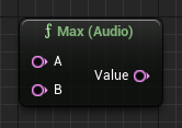
The Max node returns the higher value (max) of A and B. This node has different versions to support several common data types, including: Audio, Float, and Int32.
| Input |
Description |
| A / B |
The input values to compare. |
Max Outputs
| Output |
Description |
| Value |
The higher value (max) of A and B. |
Min

The Min node returns the lower value (min) of A and B. This node has different versions which support several common data types, including: Audio, Float, and Int32.
| Input |
Description |
| A / B |
The input values to compare. |
Min Outputs
| Output |
Description |
| Value |
The lower value (min) of A and B. |
Modulo
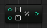
The Modulo node returns the remainder of a division operation of two given Int32 values.
Multiply

The Multiply node performs multiplication operations on provided inputs. This node has different versions which support several common data types, including: Audio by Float, Audio, Float, Int32, and Time by Float.
This node can be used to provide ring-modulation type effects and audio-rate amplitude modulation.
Power

The Power node raises a given Float to the power of another Float.
Subtract

The Subtract node performs subtraction operations on provided inputs. This node has different versions which support several common data types, including: Audio, Float, Int32, and Time.
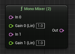
Mix
MetaSounds provide two node types to create audio mixes, the Mono Mixer node and the Stereo Mixer node. These nodes have different versions which support between 2 and 8 input audio buffers, which are combined into a single buffer by using the input channel's corresponding gain values and summing them together.
The gain values are not clamped so they can be used for attenuating and inverting the audio signal.
These nodes are useful for mapping audio-rate buffers to different ranges for modulating various audio-rate-capable parameters.
Mono Mixer
Stereo Mixer

Music
Frequency To MIDI

The Frequency To MIDI node converts a frequency value (in Hz) to a standard MIDI scale note value (where middle C is 60).
| Input |
Description |
| Frequency In |
The input frequency value (in Hz). |
Frequency To MIDI Outputs
| Output |
Description |
| Out MIDI |
The output MIDI note value. |
MIDI Note Quantizer

The MIDI Note Quantizer node quantizes a MIDI note to the nearest note that matches the provided criteria.
| Input |
Description |
| Note In |
The MIDI note to quantize. |
| Root Note |
The MIDI note to treat as the root. For example, a value of 0 equals C, a value of 1 equals C#/Db, and so on. The octave does not matter. Additionally, all values less than 0 clamp to 0. |
| Scale Degrees |
An array containing a set of notes (in ascending order) representing half steps. The array must start with 0.0 to represent the root note and the highest value in the array must represent the root note in a higher octave, such as 12.0 for a single octave range or 24.0 for a two octave range. |
MIDI Note Quantizer Outputs
| Output |
Description |
| Note Out |
The quantized note. |
MIDI To Frequency

The Frequency to MIDI node converts a standard MIDI scale note value (where middle C is 60) to a frequency value (in Hz). This node has two different versions which support Float and Int32 data types respectively.
You can use this node to musically control generators that take frequencies (in Hz) as an input. Additionally, the Float version can take fractional MIDI note values, which can be useful for microtonality and custom tuning.
| Input |
Description |
| MIDI In |
The input value which represents a MIDI note value. |
MIDI To Frequency Outputs
| Output |
Description |
| Out Frequency |
The output frequency value (in Hz). |
Scale to Note Array

The Scale to Note Array node returns an array of floating-point numbers representing notes of the selected scale.
This node can be useful when creating procedural music by using the Chord Tones Only toggle to switch between full scale and chord tones.
| Input |
Description |
| Scale Degrees |
The preset scale to get the notes for. |
| Chord Tones Only |
If enabled, a subset of the scale representing chord tones is returned. For example, scale degrees of 1, 3, 5, and 7. |
Scale to Note Array Outputs
| Output |
Description |
| Scale Array Out |
The array representation of the scale as half-steps above the root. The set is inclusive at both ends (starting at 0.0f and ending at 12.0f). |
Random

MetaSounds provide several Random nodes categorized by their output value type, including Bool, Float, Int, and Time. These nodes output a random value from their input type and a seed.
Using the Reset trigger with an identical seed will produce the same results. This is useful to get randomized repetition.
| Input |
Description |
| Next |
The trigger on which to generate the next random value. |
| Reset |
The trigger on which to reset the random sequence with the supplied seed. |
| Seed |
The seed value to use for the randomization. The default value of -1 uses a random seed. |
| Min / Max |
The inclusive range of the random value. |
Random Outputs
| Output |
Description |
| On Next |
Triggers when the Next input is triggered. |
| On Reset |
Triggers when the Reset input is triggered. |
| Value |
The randomly generated value. |
Spatialization
ITD Panner

The ITD Panner node pans an input audio signal using an interaural time delay method.
| Input |
Description |
| In |
The input audio to spatialize. |
| Angle |
The sound source angle (in degrees). A value of 90 degrees is front, 0 degrees is right, 270 degrees is behind, and 180 degrees is left. |
| Distance Factor |
The normalized distance factor (0.0 to 1.0) to use for Interaural Level Difference (ILD) calculations. A value of 0.0 is near and a value of 1.0 is far. The further away the input audio is, the less difference in levels (gain) between the ears. |
| Head Width |
The width (in centimeters) of the listener's head. |
ITD Panner Outputs
| Output |
Description |
| Out Left / Right |
The audio output (left / right channel). |
Mid-Side Decode

The Mid-Side Decode node converts a stereo signal with mid and side channels to left and right channels.
| Input |
Description |
| In Mid / Side |
The audio channels to convert. |
| Spread Amount |
The amount of stereo spread. A value of 0.0 produces no spread, a value of 0.5 is the original signal, and a value of 1.0 is fully wide. |
| Equal Power |
If enabled, an equal power relationship between the input audio channels will be maintained. |
Mid-Side Decode Outputs
| Output |
Description |
| Out Left / Right |
The output audio channels. |
Mid-Side Encode

The Mid-Side Encode node converts a stereo signal with left and right channels to mid and side channels.
| Input |
Description |
| In Left / Right |
The audio channels to convert. |
| Spread Amount |
The amount of stereo spread. A value of 0.0 produces no spread, a value of 0.5 is the original signal, and a value of 1.0 is fully wide. |
| Equal Power |
If enabled, an equal power relationship between the input audio channels is maintained. |
Mid-Side Encode Outputs
| Output |
Description |
| Out Mid / Side |
The output audio channels. |
Stereo Panner

The Stereo Panner node pans an input audio signal to left and right outputs.
| Input |
Description |
| In |
The input audio signal to pan. |
| Pan Amount |
The amount to pan the audio signal (-1.0 is fully left, 1.0 is fully right). |
| Panning Law |
The panning law to use:
- Equal Power: The power of the audio signal is constant while panning.
- Linear: The amplitude of the audio signal is constant while panning.
|
Stereo Panner Outputs
| Output |
Description |
| Out Left / Right |
The output audio signal (left / right channels). |
Triggers
Trigger Accumulate

The Trigger Accumulate node triggers once all connected input triggers have been triggered at least once. There are multiple versions of this node in order to support different input counts (between 1 and 8).
This node is can be useful to detect when multiple Wave Player nodes to finish before triggering the On Finished Output trigger.
| Input |
Description |
| In X |
The trigger input(s). |
| Auto Reset |
The trigger on which the accumulation on this node is reset. |
Trigger Accumulate Outputs
| Output |
Description |
| Out |
Triggers when all input triggers have been accumulated. |
Trigger Any

The Trigger Any node triggers once any of the connected input triggers activate. This node has different versions which support different input counts (between 2 and 8).
This is a useful node when you want to have many different trigger sources execute another node's input.
| Input |
Description |
| In X |
The trigger input(s). |
Trigger Any Outputs
| Output |
Description |
| Out |
Triggers when any input trigger is triggered. |
Trigger Compare

The Trigger Compare node triggers either true or false based on comparing connected inputs. This node has different versions which support several common data types, including: Bool, Float, and Int32.
| Input |
Description |
| Compare |
The trigger on which to compare A and B. |
| A / B |
The values to compare. |
| Type |
The type of comparison to make: Equals, Not Equals, Less Than, Greater Than, Less Than Or Equals, or Greater Than Or Equals |
Trigger Compare Outputs
| Output |
Description |
| True / False |
Triggers with the resulting trigger after making the comparison. |
Trigger Control

The Trigger Control node provides controls to allow or block trigger signals from passing through to the output.
| Input |
Description |
| Trigger In |
The input trigger to control. |
| Open |
The trigger on which to allow the input trigger to pass through. |
| Close |
The trigger on which to block the input trigger to pass through. |
| Toggle |
The trigger on which to toggle the open/closed state of this node. |
| Start Closed |
If enabled, the node will start in a closed state. |
Trigger Control Outputs
| Output |
Description |
| Trigger Out |
The output trigger that passes through if the node is open. |
Trigger Counter

The Trigger Counter node counts the connected input trigger activations.
This node is useful for sequencing array inputs and a large number of other procedural use cases.
| Input |
Description |
| In |
The input trigger for which to count activations. |
| Reset |
The trigger on which to reset the counter to zero and the value back to the start value. |
| Start Value |
The value to start with on initialization and when reset. |
| Step Size |
The value to add to the current value for each input trigger. This can be negative. |
| Reset Count |
The number of input triggers to count before automatically resetting. If the value is set to 0, the node won't automatically reset. |
Trigger Counter Outputs
| Output |
Description |
| On Trigger |
Triggers when the input trigger is triggered and the count is updated. |
| On Reset |
Triggers when the input reset is triggered or if the counter automatically resets. |
| Count |
The current trigger count. |
| Value |
The current value. |
Trigger Delay

The Trigger Delay node executes a trigger after a given delay time from the most recent execution of the input trigger.
This node is similar to the Trigger Pipe node, but differs by only considering the most recent trigger execution. This means that additional triggers that happen within the delay time will reset the timer and cause the output trigger to be delayed again.
| Input |
Description |
| In |
The input trigger to delay. |
| Reset |
The trigger on which to reset the delay and clear the execution task, if it is pending. |
| Delay Time |
The amount of time to delay the trigger (in seconds). |
Trigger Delay Outputs
| Output |
Description |
| Out |
The delayed output trigger. |
Trigger Filter

The Trigger Filter node responds to a trigger by randomly activating one of the two output triggers.
| Input |
Description |
| Trigger |
The trigger on which to randomly activate an output trigger. |
| Reset |
The trigger on which to reset the random sequence with the provided seed. |
| Seed |
The seed value to use for the randomization. A value of -1 will use a random seed. |
| Probability |
The probability that a particular output trigger will get activated. For example, a value of 0.0 is always heads, a value of 1.0 is always tails, and 0.5 is equal odds. |
Trigger Filter Outputs
| Output |
Description |
| Heads / Tails |
The possible output triggers. |
Trigger On Threshold

The Trigger On Threshold node operates as an edge detector and triggers when the input audio crosses a given threshold value while moving in the specified direction. This node has different versions which support several common data types, including: Audio, Float, and Int32.
If set to Rising Edge, a trigger is output when the signal crosses the threshold with a positive slope. This is useful when paired with a generator node and connected to another generator's sync trigger input.
| Input |
Description |
| In |
The input audio signal. |
| Threshold |
The threshold at which to trigger output. |
| Type |
The type of trigger threshold: Rising Edge, Falling Edge, or Abs Threshold |
Trigger On Threshold Outputs
| Output |
Description |
| Out |
The output threshold trigger. |
Trigger On Value Change

The Trigger On Value Change node triggers when a given value changes. This node has different versions which support several common data types, including: Bool, Float, and Int32.
| Input |
Description |
| Value |
The input value to watch. |
Trigger On Value Change Outputs
| Output |
Description |
| Trigger |
The output trigger. |
Trigger Once

The Trigger Once node triggers the first time an input trigger is activated and ignores all other occurrences, unless reset.
| Input |
Description |
| Trigger In |
The input trigger. |
| Reset |
The trigger on which to open the node and allow another trigger through. |
| Start Closed |
If enabled, the node is closed when playback begins. |
Trigger Once Outputs
| Output |
Description |
| Trigger Out |
The output trigger. |
Trigger Pipe

The Trigger Pipe node delays execution of all input trigger signals by the given delay.
This node is similar to the Trigger Delay node, but does not reset the timer upon receiving additional triggers.
| Input |
Description |
| In |
The input trigger to delay. |
| Reset |
The trigger on which to reset the trigger delay and clear any pending execution tasks. |
| Delay Time |
The time to delay the input trigger (in seconds). |
Trigger Pipe Outputs
| Output |
Description |
| Out |
The delayed output trigger. |
Trigger Repeat

The Trigger Repeat node emits a trigger periodically at a given sample-accurate and arbitrarily-precise rate.
| Input |
Description |
| Start / Stop |
The triggers on which to start or stop executing periodic output triggers. |
| Period |
The period to trigger (in seconds). |
Trigger Repeat Outputs
| Output |
Description |
| RepeatOut |
The periodically generated output trigger. |
Trigger Route

The Trigger Route node routes different input values to a single output value. This node has multiple versions for different input counts (between 2 and 8) and for each supported data type, including: Audio, Bool, Float, Int32, and Time.
| Input |
Description |
| Set X |
The input triggers which initialize the routing. The default option is 0. |
| Value X |
The input value to route to the output when triggered by its corresponding trigger. |
Trigger Route Outputs
| Output |
Description |
| On Set |
Triggers when any of the input triggers are set. |
| Value |
The output value set by an activated input trigger. |
Trigger Select

The Trigger Select node passes triggers through to the currently selected output trigger. This node has multiple versions for different input counts (between 2 and 8).
| Input |
Description |
| In |
The trigger to pass through. |
| Index |
The output index to trigger. If the provided value is out of range, it will be ignored. |
Trigger Select Outputs
| Output |
Description |
| Out X |
The output trigger at index X. |
Trigger Sequence

The Trigger Sequence node responds to input triggers by sending the next output trigger in a sequence. This node has multiple versions which provide different numbers of output triggers (between 2 and 8).
| Input |
Description |
| In |
The input trigger. |
| Reset |
The trigger on which to reset the sequence back to 0. |
| Loop |
If enabled, the sequence automatically loops back to 0 once all triggers have been activated. |
Trigger Sequence Outputs
| Output |
Description |
| Out X |
The trigger outputs in sequence. |
Trigger Toggle

The Trigger Toggle node toggles a Bool value on or off.
| Input |
Description |
| On / Off |
The trigger on which to toggle the Bool output on or off. |
| Init |
The initial states of the Bool. |
Trigger Toggle Outputs
| Output |
Description |
| Out |
Triggers when the Bool is toggled. |
| Value |
The current Bool value. |
Value

The Value node sets a variable value on a trigger. This node has different versions for each of the supported data types, including: Bool, Float, Int32, and String.
| Input |
Description |
| Set |
The trigger on which to write the set value to the output. |
| Reset |
The trigger on which to reset the value to the initial value. |
| Init Value |
The value to initialize the output value to. |
| Target Value |
The value to set the output to when triggered. |
Value Outputs
| Output |
Description |
| On Set |
Triggers when the value is set. |
| On Reset |
Triggers when the value is reset. |
| Output Value |
The current output value. |
