
You can use Deformer Graphs to create custom mesh deformations within Unreal Engine. After creating a custom Deformer Graph asset, you can use the Deformer Graph Editor, with its unique set of Blueprint nodes to edit existing mesh deformation systems, such as Morph Targets and Cloth simulations, or you can create new mesh deformation systems for any Linear Skinned Mesh.
This document provides an example workflow of how to create a custom Deformer Graph to apply a twisting mesh deformation to a Skeletal Mesh character at runtime.
Prerequisites
- Enable the Deformer Graph plugin. Navigate in the Menu Bar to Edit > Plugins and locate the Deformer Graph in the Animation section, or using the Search Bar. Enable the plugin and restart the Editor.

- Your project contains a Skeletal Mesh Character. We used the Unreal Engine mannequin in the example workflow, and you can access it in the Third Person Template.
Create a Custom Deformer Graph
In the Details panel of your Skeletal Mesh Character, enable the Mesh Deformer property and then select the Deformer Graph option from the drop down menu to create a new Deformer Graph asset.

After creating the asset, open the Deformer Graph Editor by double-clicking the asset in the Mesh Deformer property. In the Deformer Graph's Details panel, use the drop down menu in the Mesh property to select the mesh you are modifying.

From the Pallet panel, drag-and-drop the Skeletal Mesh Component Binding into the Deformer Graph's Update Graph to read the mesh's data.

Next, to rewrite the mesh's position data, add the Write Skinned Mesh node to the Update Graph and connect the Skeletal Mesh component binding.

Add and connect the Execute Skinned Mesh to the Skeletal Mesh component binding to set the domain of the mesh deformation. Select the node and change the Domain property to the Vertex option.

Next, add and connect the Scene Data node to the Skeletal Mesh component binding, to extract information about the scene the mesh occupies. This workflow uses the Time data to drive the mesh deformation at runtime.

To read the position of the vertices of the skeletal mesh, add the Skinned Mesh node and connect it to the Skeletal Mesh component binding. This node provides the Position, Tangent X, and Tangent Y coordinates for the characters mesh vertices.

Now, add a Custom Compute Kernel to the Update Graph. The Custom Compute Kernel performs the actual mesh deformation calculations using HLSL (High-Level Shader Language) programming.

Before writing the driving HLSL programming, or connecting the node to any other nodes in the graph, you must create the input and output pins, which are used by the HLSL program to perform the mesh deformation. In the Details panel of the Custom Compute Kernel, add the following input pins to make use of the information extracted from the Skeletal Mesh Component Binding using the various Read nodes.

| Pin | Data Type | Domain | Description |
|---|---|---|---|
Num Threads |
Int Vector 3 | Parameter | The Num Threads pin can accept the Domain of the mesh deformation from the Execute Skinned Mesh node's output pin. |
Twist |
Float | Parameter | Using a Constant or Variable value, this input pin determines the degree of the maximum amount of twist the mesh deforms. |
Start |
Float | Parameter | Using a Constant or Variable value, this input pin determines the start position of the twist on the Mesh's Z axis, in Unreal Engine Units (cm). |
End |
Float | Parameter | Using a Constant or Variable value, this input pin determines the end position of the twist on the mesh's Z axis, in Unreal Engine Units (cm). |
Time |
Float | Parameter | This variable input pin draws the game time from the mesh at runtime. |
Position |
Vector 3 | Vertex x1 | This input pin reads the position of each mesh axis at runtime. |
Tangent X |
Vector 4 | Vertex x1 | This input pin reads the tangent value of the X axis. |
Tangent Y |
Vector 4 | Vertex x1 | This input pin reads the tangent value of the Z axis. |
Connect the Execute Skinned Mesh node's Num Threads output pin to the Custom Compute Kernel node's Num Threads input pin. Then set the Execution Domain property to the Vertex setting in the Custom Compute Kernel's Details panel.

Next, add the following Output pins in the Custom Compute Kernel's Details panel, to output the deformed mesh data for the Write Skinned Mesh node to write back to the Skeletal Mesh.

| Pin | Data Type | Domain | Description |
|---|---|---|---|
Out Position |
Vector 3 | Vertex x1 | Outputs the newly deformed axis positions of the mesh vertices. |
OutTangentX |
Vector 4 | Vertex x1 | Outputs the modified tangent value on the X axis. |
OutTangentZ |
Vector 4 | Vertex x1 | Outputs the modified tangent value on the Z axis. |
Save and Compile the asset.

Then ensure your Custom Compute Kernel's Declarations (Read-Only) tab in the Shader Text Editor panel registers all of the input and output pins as HLSL declarations.

The Decelerations (Read Only) tab should contain the following text:
Decelerations (Read Only)
// Parameters and resource read/write functions
int3 ReadNumThreads();
float ReadTwist();
float ReadStart();
float ReadEnd();
float ReadTime();
uint GetVertexCount();
float4 ReadTangentX(uint VertexIndex);
float4 ReadTangentZ(uint VertexIndex);
float3 ReadPosition(uint VertexIndex);
void WriteOutTangentX(uint VertexIndex, float4 Value);
void WriteOutTangentZ(uint VertexIndex, float4 Value);
void WriteOutPosition(uint VertexIndex, float3 Value);
// Resource Indexing
uint Index; // From SV_DispatchThreadID.x
Next, in the Shader Text section of the Shader Text Editor panel, input the following HLSL program to perform the vertex deformation on the Skeletal Mesh.
Shader Text Editor
if (Index > ReadNumThreads().x) return;
float3 Position = ReadPosition(Index);
float4 LocalTangentX = ReadTangentX(Index);
float4 LocalTangentZ = ReadTangentZ(Index);
float Twist = ReadTwist();
float Start = ReadStart();
float End = ReadEnd();
float Time = sin(ReadTime());
float posz = min(max(Position.z, Start), End) / (End-Start);
float theta = posz * Twist * 0.0174533 * Time;
float sint = sin(theta);
float cost = cos(theta);
float3 TwistPosition;
TwistPosition.x = Position.x * cost - Position.y * sint;
TwistPosition.y = Position.x * sint + Position.y * cost;
TwistPosition.z = Position.z;
float3 TangentX;
TangentX.x = LocalTangentX.xyz.x * cost - LocalTangentX.xyz.y * sint;
TangentX.y = LocalTangentX.xyz.x * sint + LocalTangentX.xyz.y * cost;
TangentX.z = LocalTangentX.xyz.z;
float3 TangentZ;
TangentZ.x = LocalTangentZ.xyz.x * cost - LocalTangentZ.xyz.y * sint;
TangentZ.y = LocalTangentZ.xyz.x * sint + LocalTangentZ.xyz.y * cost;
TangentZ.z = LocalTangentZ.xyz.z;
float4 TwistTangentX = float4(normalize(TangentX), LocalTangentX.w);
float4 TwistTangentZ = float4(normalize(TangentZ), LocalTangentZ.w);
WriteOutPosition(Index, TwistPosition);
WriteOutTangentX(Index, TwistTangentX);
WriteOutTangentZ(Index, TwistTangentZ);
After adding the custom HLSL program to calculate the mesh deformation, connect the read and write nodes to the associated input and output pins on the Custom Compute Kernel node.

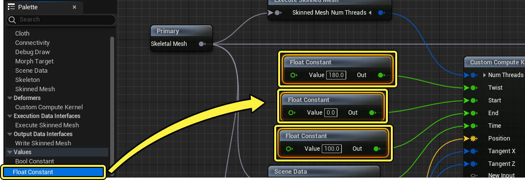
Finally, drag-and-drop three Float Constant nodes from the Pallet panel to the Update Graph to set the Twist, Start, and End values for the custom function. Connect one Float Constant node to each of the three available input pins on the Custom Compute Kernel node. Set the Float Constant node connected to the Twist input pin to a value of 180.0, the Float Constant node connected to the Start input pin to a value of 0, and the Float Constant node connected to the End input pin to a value of 100.0.
Alter these values to see how the function's inputs are modified, to dynamically change the deformation. Instead of constant values, the function is driven using Deformer Graph variables, Resources or animation curves.
Save and Compile the asset to see the mesh now twisting in the Preview Viewport panel as well as in the level in real time.

You can add the custom Deformer Graph to any character in a level, by selecting the mesh, and navigating to the Deformers section of its Details panel. You can assign the custom Deformer Graph to the character by enabling the Deformer Graph property, and selecting the custom graph from the drop down menu.
For more information about Deformer Graphs or the Deformer Graph Editor and Blueprint nodes, refer to the Deformer Graph documentation.
This and other application examples of mesh deformations controlled by custom Deformer Graph logic are present in the Content Examples.
For more information about HLSL (High-Level Shader Language)programming used to drive the Deformer Graph's Custom Compute Kernels, refer to the Microsoft High-Level Shader Language reference documentation and programming guide
Graph Reference
Here you can use the image slider to reference the full Deformer Graph, Custom Compute Kernel Details panel, and Shader Text Editor panel, used in the workflow example.


Reference Images