
This guide will walk you through the details of the Advanced Vehicle template. By the end of the guide, you will understand how the set up works in theory and how to configure a similar vehicle in the engine.
To follow along, download the assets here. These FBX files should be used with the Advanced Vehicle project template available in Unreal Engine.
The double wishbone suspension is a more advanced setup compared to the default vehicle from the template. We recommend you read the How to Setup Vehicles documentation before following this guide.
Simulated Wheels Versus Real Suspension Linkages
When you set up the vehicle movement component and assign wheels to it, the vertical movement of the wheels is updated by a WheelHandler node inside the vehicle's animation Blueprint. On each frame, the handler will move the wheels up and down along the local Z axis to simulate the suspension, making sure that the wheels touch the ground whenever possible.
The WheelHandler also applies rotation to make the wheels spin around their Y axis, driven by the rotation speed of the simulated motor and gearbox. In addition to this, it will turn the wheels around their Z axis, driven by the current steering angle.
The default vertical suspension movement is clamped by the Suspension Max Raise and Drop settings in your VehicleWheel-derived classes. This movement is entirely linear, as illustrated below:
The standard vertical movement produced by the WheelHandler.
This type of suspension simulation works for most vehicles, as you cannot usually see the suspension arms or the other components such as the springs and shocks. However, in a more open vehicle like a buggy, where the moving parts are in view, this movement can be problematic, as there is no suspension design that would be able produce this kind of movement.
To achieve a more realistic result, we need motion that can be expressed as a rotation around a fixed pivot point on the vehicle's body:
Ideal vertical and lateral movement.
You can create similar movement by having the simulated wheel nodes controlled by the WheelHandler, and having separate wheels for rendering. Then you can feed data supplied by the WheelHandler to the rest of the suspension setup to get the desired results. In short, the visible wheel and the simulated wheel are two different objects.
The wheel parameters you define in the VehicleWheel class can specify the Collision Mesh, Radius and Width of each wheel. Those specifications do not have to correspond to any geometry in the vehicle's Skeletal Mesh, so there is no need for the simulated wheel nodes in the Mesh to have any real geometry. Furthermore, you can specify additional wheel offsets in the Wheel Setup section of the Vehicle Blueprint, so the pivot of the wheels do not have to be aligned with the geometrical center of the visible wheel Mesh.
Skeletal Nodes
In the Content Browser, go to Vehicles > Vehicle and double click VehicleAnimationBlueprint to open it.
You already learned about the WheelHandler node, so we will focus on the CopyBone and LookAt nodes in this section. They perform the same tasks as position, rotation, and aim constraints in applications such as Maya.
Copy Bone
The CopyBone node can copy transformation data from one bone (the source) to another bone (the target):
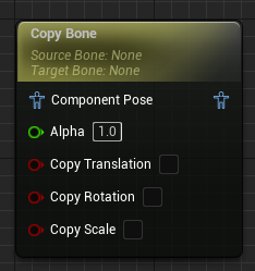
The CopyBone animation Blueprint node and its default settings.
This means that once the WheelHandler has updated the transformation of the simulated wheels, you can grab the rotation values it has produced and apply them to your visible wheels. This basic step will take care of spinning and steering the wheels, while avoiding getting the translation (position) data.
Look At
The LookAt node can rotate any given bone in such a way that one of its axis ends up aiming at another bone.
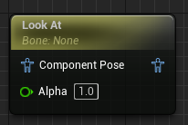
The LookAt animation Blueprint node and its default settings.
This is useful, as it gives you a way to make sure that all the components of the suspension mechanism are constantly updated to point in the right direction - all driven directly or indirectly by the current position of the simulated wheels. This will be used for several bones in the animation Blueprint.
Implementation Overview
Each of the four wheels we will use one invisible wheel for the WheelHandler to manage, and one visible wheel that is rendered in game. The former is a single bone/joint, while the latter is a wheel-like Mesh you build in a modeling package and add to the vehicle model.
For everything to work as intended, key parts of the suspension will copy the transformation data they need from other bones, or adjust their orientation by looking at targets that you have set up in the model.
Constructing the Model
Open Assets/FBX/vehicle_proto_S2.9.fbx in your main modeling application so you can follow along and see how everything fits together.
The vehicle prototype created for this tutorial has a suspension rig designed like this:
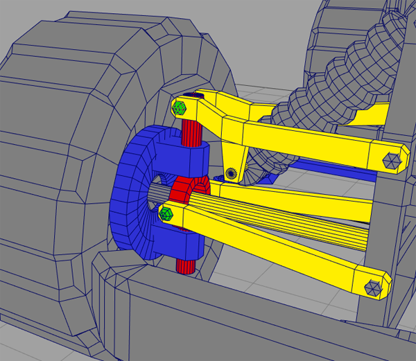
Close-up on the front right suspension of the prototype vehicle. The colors have been added to this illustration for clarity - they are not assigned to materials in the FBX file.
The key components are the upper and lower arms (yellow), the kingpin (red) and the hub (blue). Both arms pivot around their respective hexagonal bolts seen in the far right of the image.
The central point where everything comes together is close to the green bolt on the lower arm. That is where the simulated wheel joint, PhysWheel_[loc], is initially located. The kingpin, hub, and visible wheel also have their pivots at that exact same location.
Each one of these components has a very strict transformation range. The arms rotate only around their forward axis. The kingpin follows the position of the tip of the lower arm, but stays vertical at all times and never rotates relative to the vehicle. The hub rotates around its vertical axis only, in response to steering. The visible wheel copies its rotation from the simulated wheel, but takes its position from the tip of the lower arm. This keeps everything tightly locked together.
In any complex rig, it is very important to keep the hierarchy and update order in mind. In this particular case: when the lower arm rotates, it must bring with it a child Mesh (lower green bolt) that the kingpin subsequently needs in order to position itself correctly using a CopyBone node. The upper arm, in turn, needs access to the updated position of a child Mesh (near the upper green bolt) of the kingpin in order to have something to aim at using a LookAt node, and so on. As you can see, it is essential to make sure that the different components are updated in the correct order, otherwise parts of the suspension may appear to lag behind the movement of other parts.
All these frame-by-frame updates are handled by the animation Blueprint.
When building the model in a DCC (Digital Content Creation) application, you only have to worry about the hierarchy and the exact position and orientation of the component pivots. A sensible orientation is particularly important for components that will have their rotation updated by LookAt nodes.
As a general note, it can be helpful to use the constraints offered by your modeling package while designing this kind of mechanism. They will not follow the FBX into Unreal Engine on import, but sometimes it is easier to figure out what needs to be done if you can get the basic movement while building the model. However, avoid using any constraints that you will not be able to recreate inside the animation Blueprint.
The Setup in Unreal Engine
Now let us see how this demo has been set up inside Unreal Engine. Load up the project file in the editor to follow along, and open the vehicle's animation Blueprint. Note that most of the operations are applied four times, once for each wheel.
While driving the vehicle, the following things happen in the animation Blueprint:
First, the Wheel Handler updates the position and rotation of the simulated wheels (PhysWheel bones). The visible wheels (VisWheel bones) then update their rotation by copying the rotation from the PhysWheels:
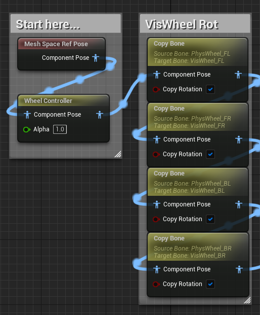
The Wheel Handler followed by Copy Rotation to the visible wheels.
This gives us a visually correct spin and steering, but the wheels will not change their position. That is handled separately in a later step.
Next, the lower arms (ArmLower bones) aim at the position of the PhysWheel. Arms on the right side of the vehicle use Y as the look at axis, while arms on the left side use Negative Y:
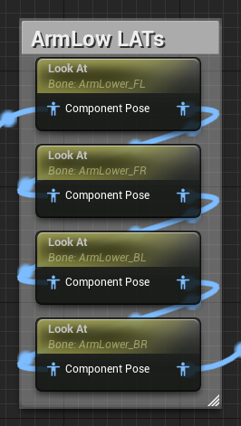
The ArmLower bones looking at the PhysWheel position.
The result of a LookAt node can easily be previewed in the 3D window of the animation Blueprint editor: the current target of a selected LookAt node is marked with a red cross. This is easier to see if you set the preview viewport to wireframe mode.
When an ArmLower bone rotates to match its LookAt target, it brings with it a child component called POS_Hub. This is used in the next step to correctly position the Kingpin using a CopyBone node which grabs only the translation of the POS_Hub bone:
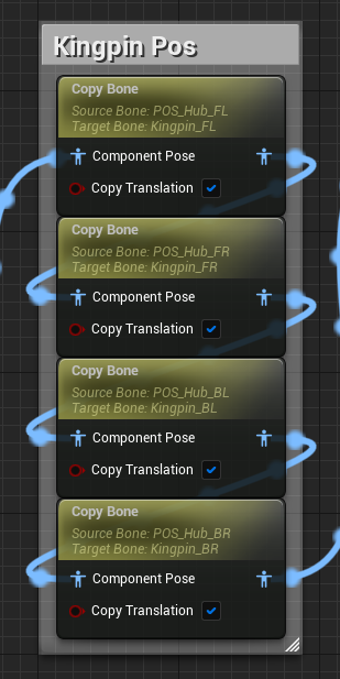
Setting the Kingpin position.
The Hub and VisWheel will later be set to the same position using the same method.
The next step adjusts the upper arms (ArmUpper bones) by looking at their respective targets (LAT_ArmUp bones) which have been placed in the correct position by the fact that these targets are children of the Kingpin bones, which were updated in the previous step:
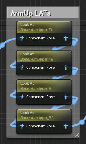
Orienting the upper arms.
After setting the position of the hubs, there is some extra work that needs to be done on the front hubs only, to account for rotation around Z caused by steering. This is handled with LookAt nodes targeting LAT_Hub bones that are children of the frontal PhysWheels:
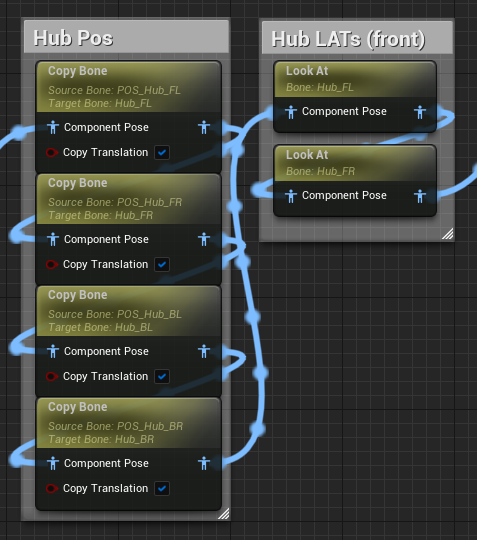
Setting Hub position and steering angle.
Finally, after setting the VisWheel positions to match the POS_Hub bones, we make sure that the upper part of the shock is aimed at the lower shockmount (ShockMount_Low), and that the lower shock bone follows the position of that very same shockmount, which is a child of the upper arm:
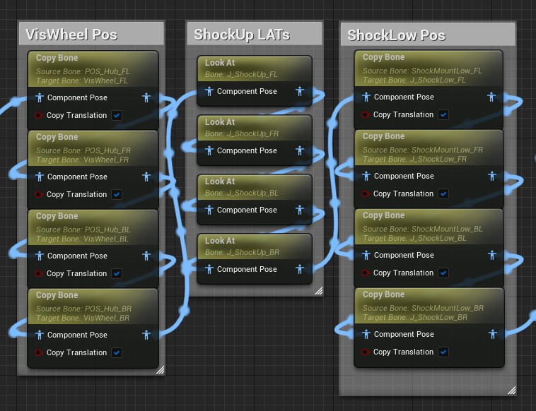
Positioning visible wheels, and adjusting shock components.
Physics Bodies Setup
Import vehicle_proto_S2.9.fbx to the engine and click the Skeleton dropdown. Select VehicleSkeleton from the list. Click Import All.
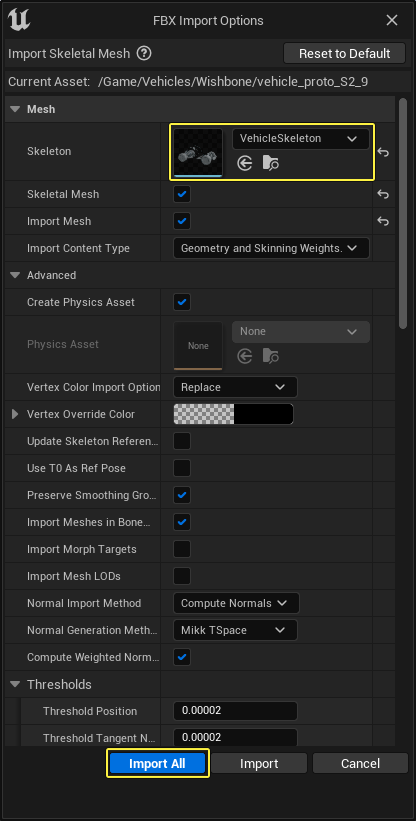
A new Skeletal Mesh and Physics Asset will be created in the Content Browser.
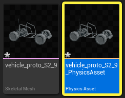
Import vehicle_collision_S2.9.fbx to the engine. A new Static Mesh asset will be created in the Content Browser.
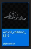
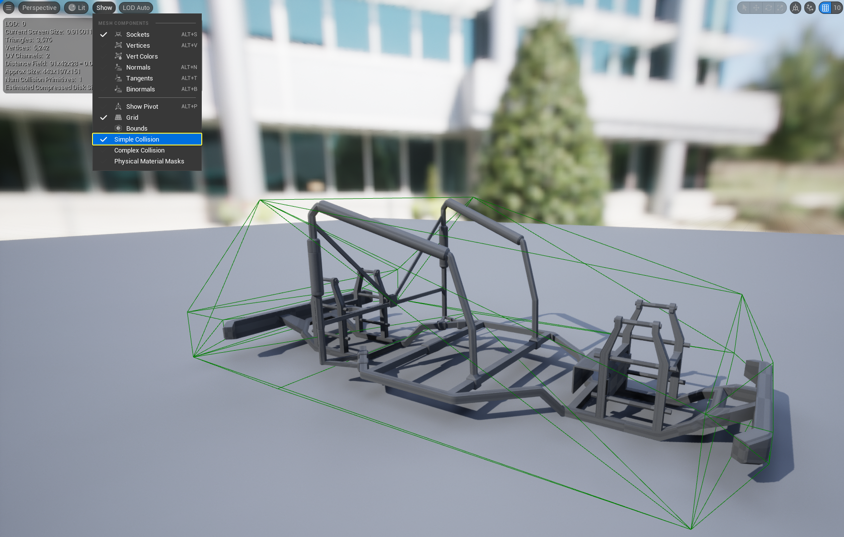
Double click vehicle_collision_S2_9 in the Content Browser to open the asset in the Mesh Editor. Click Show > Simple Collision to visualize the collision shape created for the Static Mesh. In a later step, you will use this collsion shape on the buggy's Skeletal Mesh.
In the Content Browser, double click vehicle_proto_S2_9_PhysicsAsset to open the asset in the Physics Asset Editor. You will see the default Physics Bodies created by Unreal Engine.
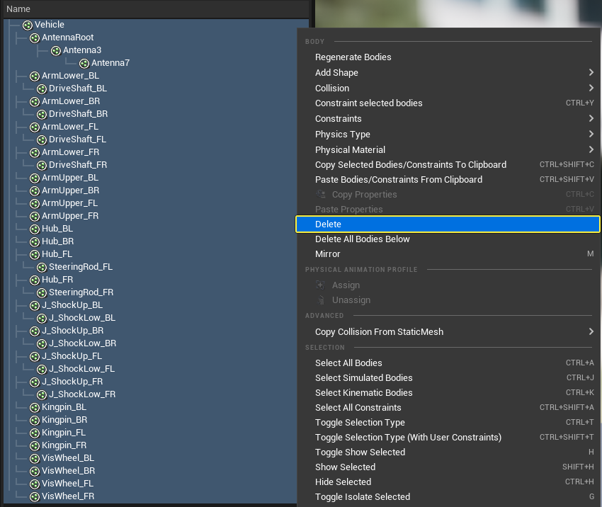
Go to the Skeleton Tree panel and select all the Physics Bodies from the list. Right click and click Delete.
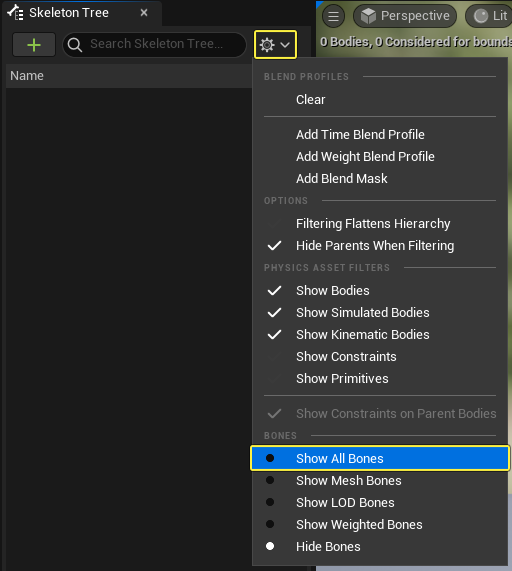
Click the Settings menu and select Show All Bones.
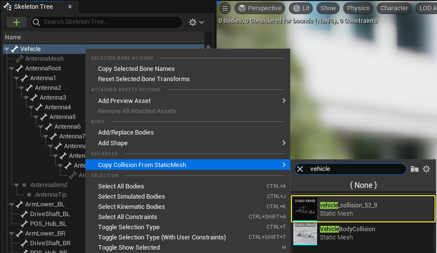
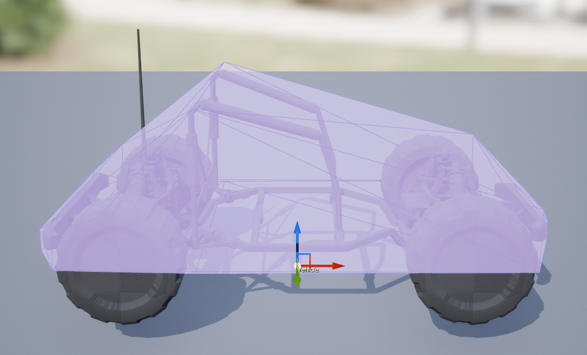
Right click on the root bone and hover over Copy Collision From StaticMesh. In the search box search for and select vehicle_collision_S2_9. This will assign the collision of the Static Mesh to the root of the buddy's Skeletal Mesh.
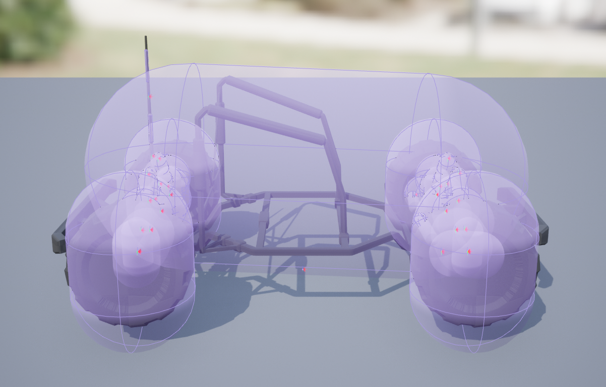
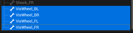
Go to the Skeleton Tree panel and select the bones for the four wheels.
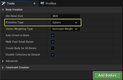
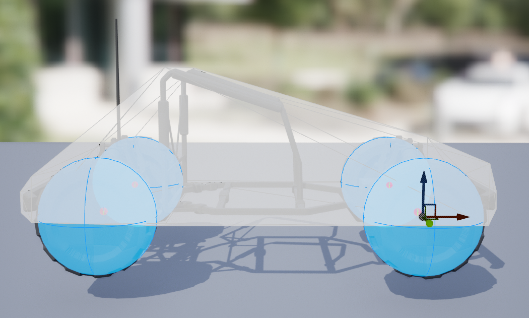
Go to the Tools panel and click on the Primitive Type dropdown. Select Sphere and click Add Bodies.
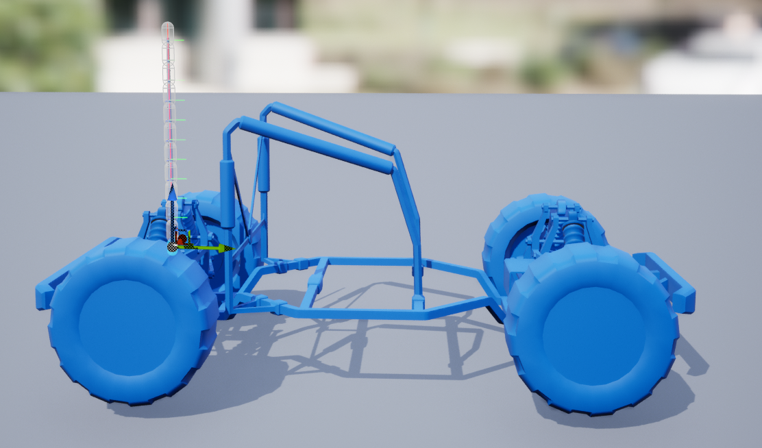
Antenna Setup
While the antenna is not part of the double wishbone suspension setup, it can still affect the overall handling of the vehicle.
The simplest solution is a rigid antenna, unaffected by physics, but this template shows how to set up an antenna that will move as you drive without negatively impacting your vehicle's movement.
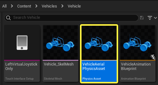
In the Content Browser, go to Vehicles > Vehicle and double click VehicleAerialPhysicsAsset to open it.
You can see how the antenna is made up of several small capsule Physics Bodies.
Go to the Skeleton Tree panel and notice how the antenna Physics Bodies are set up.
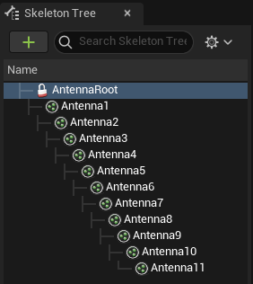
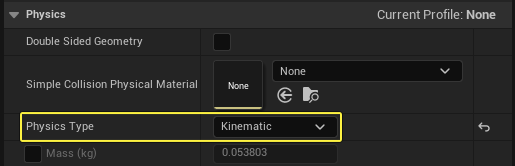
The root's Physics Type is set to Kinematic to prevent simulation.
As you select the Physics Bodies starting from the root, notice how the Mass amout decreases the farther the body gets from the root. This ensures the segments closer to the root feel heavier during simulation.
Rolling Your Own
When importing your own Skeletal Mesh, follow these tips to make your own vehicle:
-
Keep the names and the Skeleton Tree identical to the prototype. This will ensure that the Animation Blueprint can be reassigned and reused on a different Skeletal Mesh without any changes. You can add more Mesh nodes to the model, as long as it does not interfere with the overall hierarchy of the key suspension components.
-
The vehicle root should be placed at 0,0,0 in global space, and must not be rotated. Make the root a simple joint object to ensure the FBX export and import will work correcty.
-
If your modeling package allows it, set it up to use Z as the up axis and remember to use X as the forward axis.
-
The wheel Meshes should touch the floor/grid in your modeling application. Always make sure the individual components of your model have their pivots at the intended center of rotation, and their rotations are zeroed out. The shocks are the exception, where it makes more sense to orient the root and tip joints towards each other.
Credit
This project and tutorial are based on work provided by community member Xenome, and are published here with permission.
Thank you, Xenome!