
Pixel Mapping is the process of analyzing an input image or video by defining areas of interest, computing the average pixel values in each area, and then sending those values out to another system using a protocol (such as DMX) to control physical devices.
Use the DMX Pixel Mapping tool in Unreal Engine to sample the pixels of a specified texture and output the color sample as DMX. This tool integrates with the other DMX plugins in Unreal Engine, and uses the DMX Library assets and DMX Protocol functionality.
Workflow
Create A New Pixel Mapping Asset
To create a new Pixel Mapping asset, follow these steps:
- Right-click in the Content Browser, navigate to the DMX category, and select DMX Pixel Mapping.
Double-click the Pixel Mapping asset in the Content Browser to open it in the Pixel Mapping editor.
Add an Input Source
When you create a new DMX Pixel Mapper asset, a default Input Source is created for you. You can edit this Input Source, or click Add Source in the top menu bar to create a new Input Source.
After you create and select a Source, you can set the Input Texture in the Details panel under Render Settings. You can use any texture or live render target that you have available.
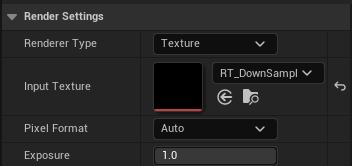
You can also adjust the following settings:
- Pixel Format: Sets the internal precision of the Pixel Mapper:
- Auto: Automatically adjusts the internal Pixel Mapper buffers precision so it matches the input texture precision.
- Low: Forces low precision (8-bit RGBA8 integer format).
- High: Forces high precision (16-bit RGBA16F floating point format).
- Exposure: Adjusts the range of the input texture values to fit wider dynamic range data. For example, an exposure of 0.25f allows a range of 0-4 to be remapped to 0-1. Since DMX converts values back to 0-1 range in high precision integer format, this allows increased value range.
Filter an Input Source
Pixel Mapper lets you apply downsample passes and add 2D filters to its Input Source.
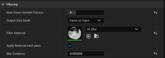
To apply downsample passes and filters to the input source, use the following settings:
- Num Down Sample Passes: The number of times to reduce the input texture size by 2 in each width and height directions. The bigger this number is, the stronger the effect of the applied blur filter Material.
- Output Size Mode: Whether to apply a custom resolution to the final render target.
- Filter Material: A Material to be applied at every downsample pass.
- Apply Material each pass: Whether to apply the material every downsample pass, or just in the last pass.
- Blur Distance: Sets the BlurDistance parameter on your Material.
Reference a DMX Library
To add a Fixture Group and reference a DMX Library, follow these steps:
- In the DMXLibrary section, click + Add Fixture Group.
- Select a DMX Library from the DMXLibrary drop-down.
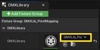
The Patches from the DMX Library will now be listed in the DMXLibrary section.
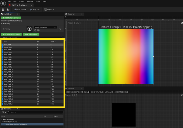
Add Patches to the Grid
To add Fixture Patches to the Grid, you can click either Add Selected Patches or Add All Patches. When a patch is added to the Grid, it is added to the list in the Hierarchy panel.
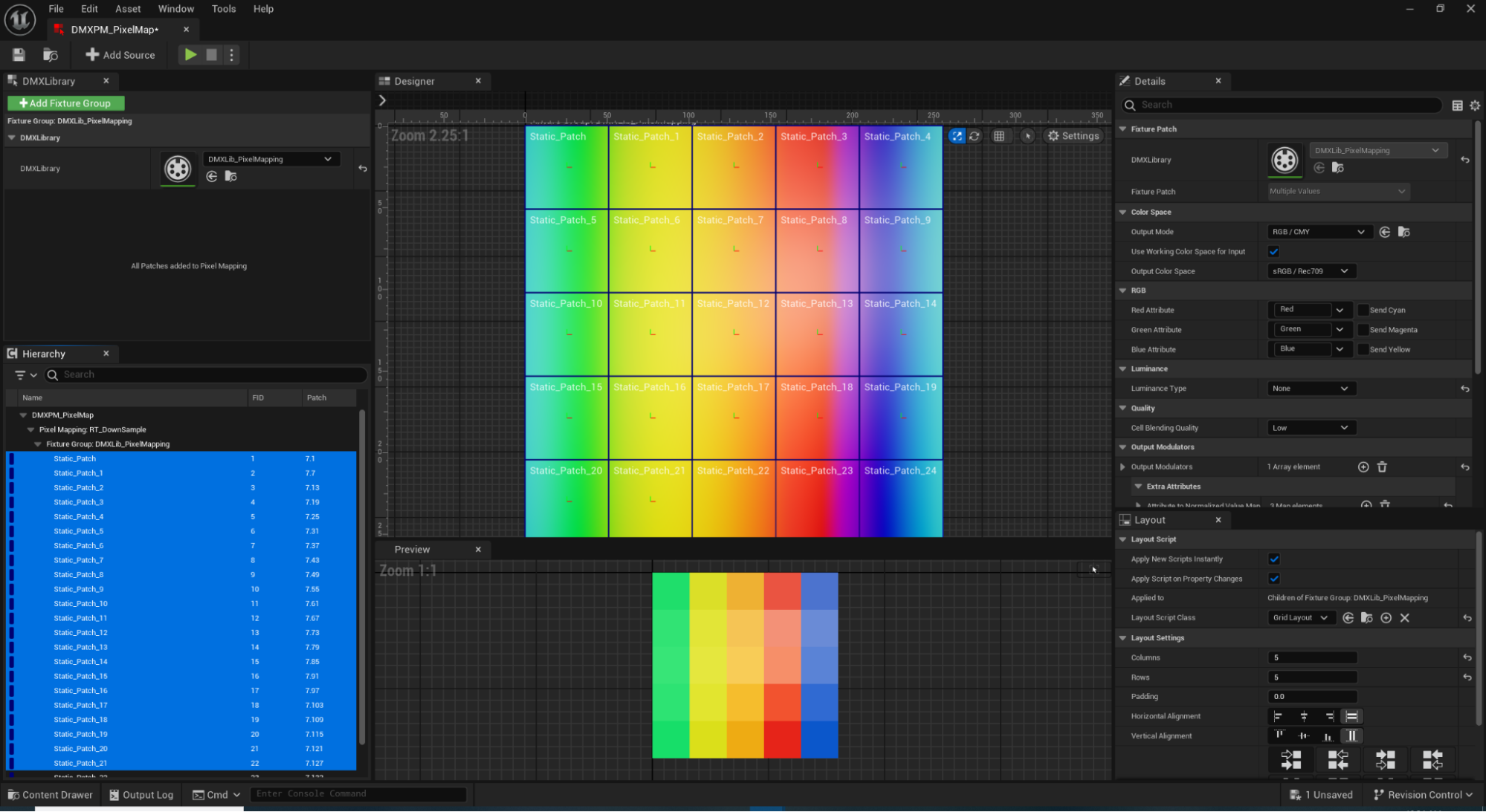
A patch can only be added to a pixel mapping once. This prevents the pixel mapping from creating conflicting DMX data.
In the Details panel, you can enable the Children Follow Size checkbox so that existing patches follow the size of the texture when the texture is changed.
Change the Patch Layout
After you've added patches to the Grid, you can change the layout of the patches automatically or manually.
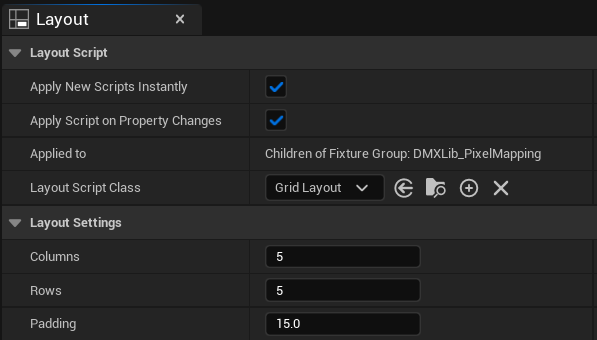
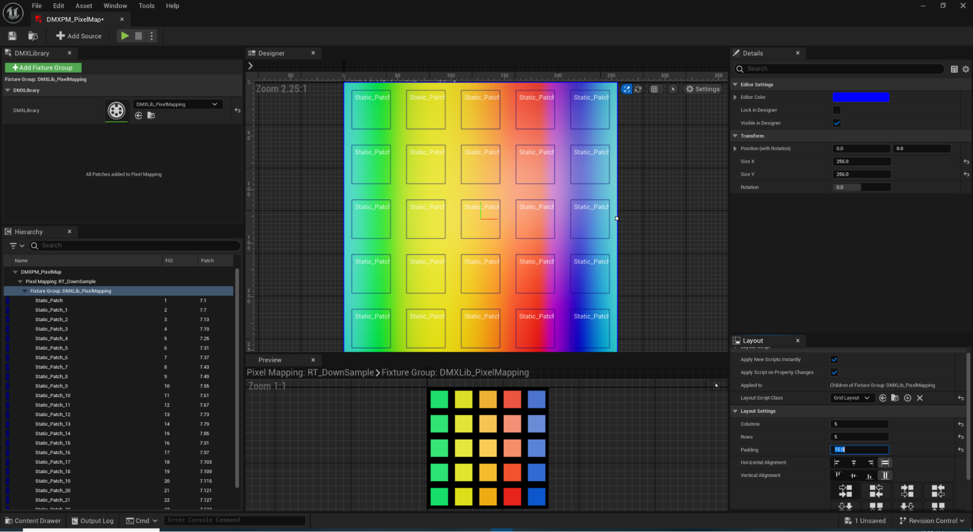
Change the Layout Automatically
To automatically arrange the patches in a grid layout, follow these steps:
- Select the Fixture Group in the Hierarchy panel.
- In the Layout panel, set the Layout Script Class to Grid Layout.
- Use the Layout Settings to change the number of columns and rows, padding, and the alignment and distribution of the cells.
Change the Layout Manually
You can manually move and resize the Fixture Patches in the Designer. Click a Fixture Patch to select it. Click and drag the Fixture Patch to move it. Click and drag the dots on the edges of the Fixture Patch to resize it.
To rotate a patch, right-click a patch in the Designer and select Rotate Mode. Click and drag the dot on the corner of the Fixture Patch to rotate it.
You can select multiple Fixture Patches, either in the Designer or the Hierarchy panel, and move or resize them as a group.
Play a Pixel Mapping Asset
Play a Pixel Mapping Asset in the Editor
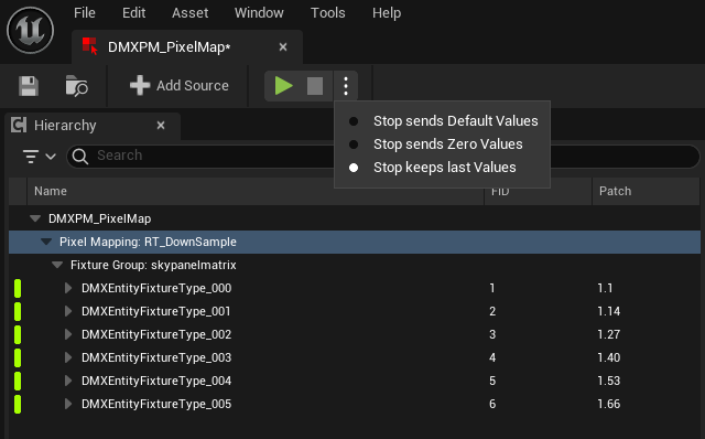
Pixel mapping assets can be played in editor. Click the Play button to send DMX data each tick. The Stop button can perform several actions, depending on the following settings:
- Stop sends Default Values: When you press Stop, the Pixel Mapping sends default values for all patches, once. The buffer will remember these values until another object sends to the same DMX addresses.
- Pause: When you press Stop, the Pixel Mapping sends zero values for all patches, once. The buffer will remember these values until another object sends to the same DMX addresses.
- Stop keeps last Values: When you press Stop, the Pixel Mapping does not send special values.
Play a Pixel Mapping Asset In-Game
- Create a new Blueprint of type Actor.
- Add a new Get DMX Pixel Mapping Renderer Component node.
- Drag from this node's Out Component pin and type "Render and Send DMX".
-
Add the Render and Send DMX node and connect its execution pin to the Tick node of the Actor Blueprint.
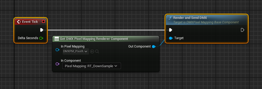
-
Drop the Actor into the level and start the game.
Settings
Designer Settings
The Settings menu, located in the Designer viewport toolbar, includes the following options:
- Always select Group: When enabled, when selecting a child component, the parent is also selected.
- Scale Children with Parent: When enabled, when resizing a parent component, its children are also resized.
- Show Component Names: Whether to show the names of Fixture Patch and Group components.
- Show Patch Info: Whether to show Patch IDs and numbers.
- Show Matrix Cells: Whether to show Matrix cells.
- Show Cell IDs: Whether to show Matrix cell IDs.
- Show Pivot: Displays the pivot of the selected Component.
- Font Size: Sets the font size in the Designer.
- Display Exposure: Sets the display of the Input Source texture. Does not affect computed data.
Grid Settings
Grid settings allow Patches to be perfectly aligned and placed in the Designer.
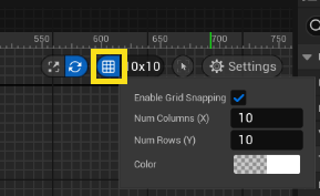
- Enable Grid Snapping: Toggles the grid snapping feature.
- Num Columns (X): Sets the number of horizontal grid cells.
- Num Columns (Y): Sets the number of vertical grid cells.
- Color: Sets a display color for the grid.
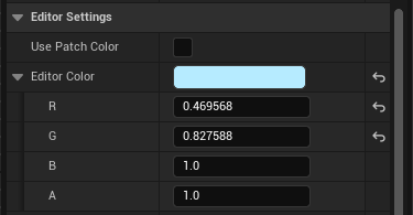
Editor Settings
Use the Editor Settings section in the Details panel to set the Editor Color, which is automatically applied to the outline of components in the Designer.
If you select one or more Patches in the Designer, you can deselect Use Patch Color and give the selected Patches a unique outline color.
Matrix Settings
Use the Matrix section in the Details panel to invert the cell ordering of the matrix. This is useful when hardware fixtures are facing away from the screen.
- Invert Cells X: Inverts the cell ordering along the X-Axis. Useful when hardware fixtures are facing away from the screen.
- Invert Cells Y: Inverts the cell ordering along the Y-Axis.
Color Space
Use the Color Space section in the Details panel to define which color space Pixel Mapping uses to send output. Unreal Engine uses RGB values internally alongside a working color space to define colors. Some physical DMX fixtures use or allow other formats.
Output Modes
The following Output Modes are available:
- RGB/CMY: The default mode where RGB DMX values are generated from RGB values from a provided rendertarget. You can set a Destination Color Space. Then, the engine Working Color Space will be converted to the provided Destination Color Space.
- CIE 1931 xyY: The engine Working Color Space will convert automatically to the xyY color space. If you uncheck Use Working Color Space for Input, then the engine Working Color Space is interpreted as RGB color space.
- CIE 1931 XYZ: The engine Working Color Space will convert automatically to the XYZ color space. If you uncheck Use Working Color Space for Input, then the engine Working Color Space is interpreted as RGB color space.
Output Gamma
Use this setting to apply a gamma curve to the sampled color values that are being sent as DMX. This setting has the following options:
- Linear: No transfer function is applied.
- As Output Color Space: The transfer function of the Output Color Space is used. For example, when Output Color Space is set to sRGB, the transfer function of sRGB is applied.
- Custom: A custom transfer function can be specified.
RGB Mode
This is where the actual mapping of the read RGB values will translate to the current Patch DMX channels. Typically, you would map the red texture value to the Red DMX channel, same for green and blue. However, you can map the alpha value to Pan/Tilt or any other available channel for other purposes.
Luminance
You can query the calculated luminance value from the read pixel and drive the Dimmer channel with it, or any other channel available. Alternatively, you can force set the Dimmer channel to a constant value and only drive RGB values from above.
Quality
This is the quality control of the computed average values from the input texture. The following quality values are available:
- High: 9 samples per Patch
- Medium: 5 samples per Patch
- Low: 1 sample per Patch
The higher the sample count, the smoother the resulting values, as they will be averaged before forming the final value to be used.