
This guide explains how to set up a modular vehicle for simulation in the Chaos Physics Solver.
The individual assets that make up a modular vehicle are as follows:
- Geometry Collection assets (for the vehicle parts - generated from Static Meshes)
- A vehicle Blueprint
Enable the Chaos Modular Vehicle Plugin
Click Edit > Plugins and search for "chaos modular vehicle". Verify the Chaos Modular Vehicle plugin is enabled for your project.
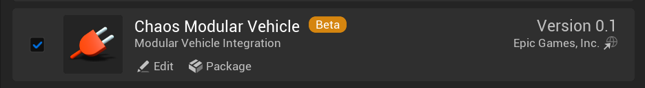
This is an entirely separate plugin from the Chaos Vehicle Plugin. You do not require both.
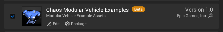
(Optional) Enable the Chaos Modular Vehicle Examples Plugin
Click Edit > Plugins and search for "chaos modular vehicle examples". Verify the Chaos Modular Vehicle Examples plugin is enabled for your project.
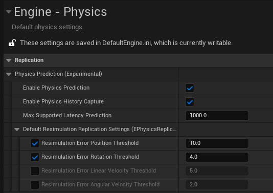
Enable the network settings
In your project settings, under Engine > Physics, click Enable Physics Prediction and Enable Physics History Capture. This gives superior networking with server authoritative client prediction with rewind resimulation behavior. The vehicle will feel like it is locally controlled with no lag from the control inputs.
Create the Geometry Collection Assets
The modular vehicle currently uses Geometry Collection assets for the vehicle parts. This is the same asset that is used with physics destruction. The destruction tools can be employed to generate geometry collections from static meshes.
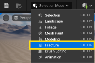
Convert each of the separate vehicle pieces from a static mesh to a Geometry Collection using the fracture tools, following these steps:
-
Drag a static mesh onto a level, and change the editor to Fracture Mode in the Main Toolbar.
-
With the static mesh asset selected, click Generate > New.
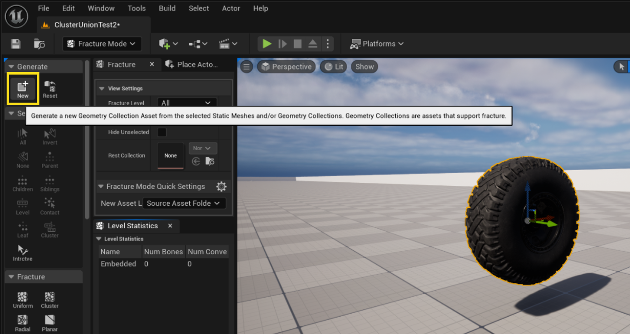
- In the Select Path window, choose a location where to save the new asset and name the asset.
- Click Generate Geometry Collection.
-
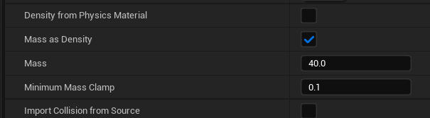
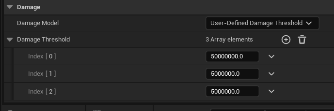
In the Details for the Geometry Collection asset, set the mass of each part and the damage threshold for how easily the part breaks off.
Repeat these steps for all other vehicle parts. You need at least two assets: an asset for the vehicle chassis and an asset for the wheel.
Create a Cluster Union Vehicle Pawn Blueprint
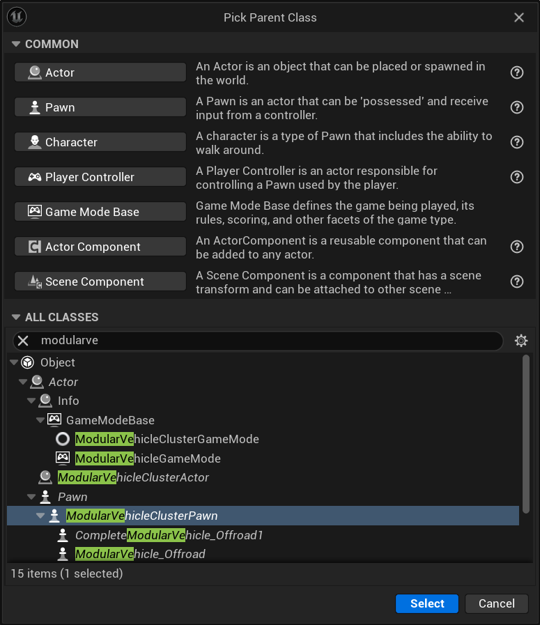
- In the Content Browser, click Add (+) > Blueprint Class.
- In the Pick Parent Class window, under All Classes, search for "ModularVehicle" and select ModularVehicleClusterPawn.
- Click Select.
The new asset appears in the Content Browser. Give it a recognizable name so that you can easily locate it later (for example, "BP_ChaosFrontWheel").
Build The Vehicle Structure in The Blueprint
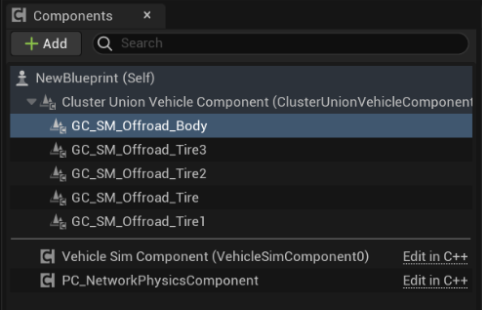
Now that you have created the Modular Vehicle Blueprint, open it in the Blueprint Editor and begin adding the Geometry Collection Components. The Cluster Union Vehicle Pawn has some default components already assigned: a Vehicle Simulation Component responsible for the modular vehicle simulation, as well as a Network Physics Component.
-
Add Geometry Collection components for each of the vehicle pieces by dragging each Geometry Collection asset into the Components panel under the Cluster Union Vehicle Component.
-
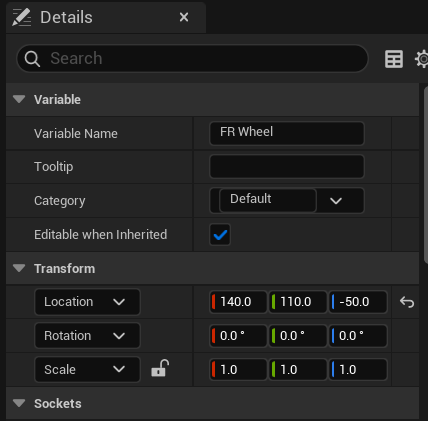
Use the Viewport to position the vehicle parts so they sit in the correct position relative to one another. For accuracy, it may be better to enter the precise location for pieces into the Details panel of the Geometry Collection component. This is particularly important for the wheels, as if they are not perfectly symmetrical, the simulation might not drive in a straight line. The convention is X forwards, Y right, Z up.
-
In the Details panel, under Chaos Physics > Clustering, enable Force Update Active Transforms. If you don’t do this, then pieces that fall off the vehicle will follow the main actor around once they come to rest. This is due to an optimisation that will stop updating the transforms when the object is not moving. Ordinarily this is fine if the geometry collection has its own actor, however here we are parented to a shared moving actor.
When using one wheel model for the entire vehicle, you might want to flip the wheels on one side of the vehicle for the wheels to look correct. This involves adding a 180 backdegree rotation to the Z rotation axis. This flipping of the axes will also require a change in the next step of this guide, when you set up of the simulation components associated with these parts.
Add Simulation Components to the Geometry Collections
Simulation components add simulation behaviors to the geometry collections. For example, if you want a geometry collection to behave like a wheel, you need to add a Wheel component.
In the Blueprint Editor, click Add (+) and search "sim" to get a list of all the available simulation options.
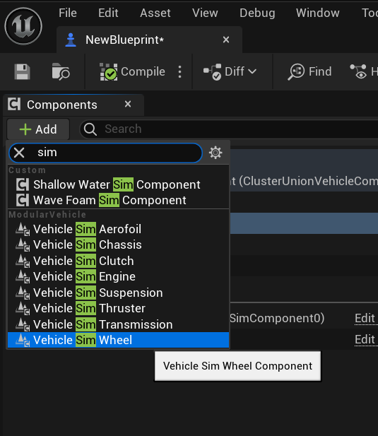
The hierarchy of the simulation components is very important. Simulation components should be a child of their parent geometry collection. For example, a VehicleSimWheel Component must be added under a Geometry Collection wheel model. The simulation uses the transform of that component to locate where the forces should be applied from, and also to turn off the simulation for that part if it is broken off. The parent-child relationship of the simulation components themselves is also important. The parent-child relationship of engine, clutch, transmission indicates the flow of torque between the modules.
To add simulation components to the geometry collections, follow these steps:
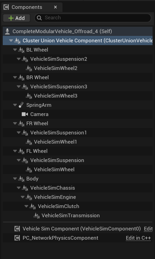
- Add a VehicleSimSuspension component under each of the geometry collection components that represents a wheel.
- Add a VehicleSimWheel component under each VehicleSimSuspension component.
- Add a VehicleSimEngine component under the vehicle chassis geometry collection component.
- Add a VehicleSimClutch component under the VehicleSimEngine.
- Add a VehicleSimTransmission component under the VehicleSimClutch.
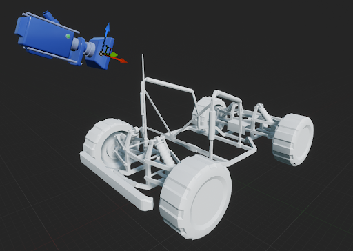
The finished setup should look like the following image.
Change all the simulation parameters in the details panel as appropriate for your vehicle. It is possible to change parameters on multiple wheel components simultaneously by holding Ctrl while selecting the components. Then, any changes you make in the details panel will apply to all of the selected components.

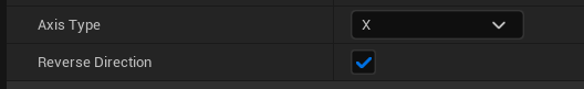
If a wheel component has been rotated in the editor to make it look right (180 degree rotation around Z) then the wheel will simulate backwards unless the Reverse Direction property is checked.
Define Vehicle Inputs
-
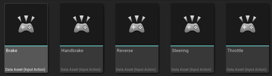
Create input actions for each of your controls.
-
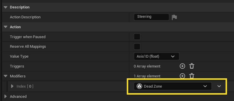
For the Steering input action, it is advisable to add a Dead Zone modifier, otherwise the steering might drift when it should be driving straight.
- In the Content Browser, click Add (+) > Input > Input Mapping Context.
-
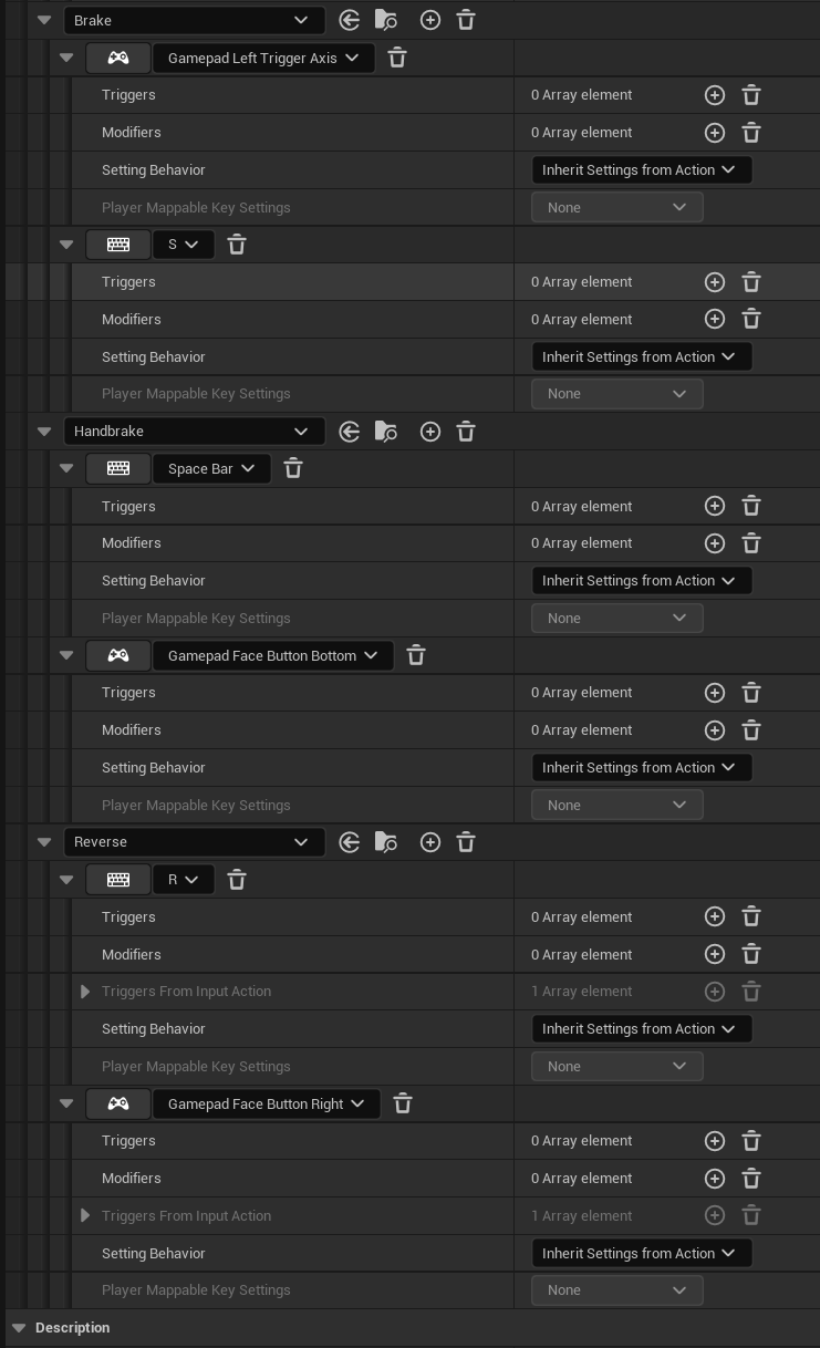
Open the input mapping context and map controls to your each of your input actions, as shown in the following images.

-
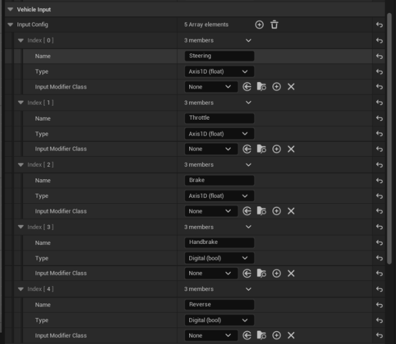
On the vehicle asset, inputs are defined by name and type. These need to match the names implemented in the modular vehicle code. The core modules use the following inputs:
Module Input Name Engine Throttle Clutch Clutch Thruster Throttle Transmission ChangeUp, ChangeDown Wheels Steering, Brake, Handbrake Aerofoil Roll, Pitch, Yaw -
On the Vehicle Simulation component, add five array members to the Vehicle Input section if they do not already exist, and fill them out in the Details panel on the right.
-
In the vehicle Blueprint, connect the EnhancedInputAction events to the vehicle as shown in the following image.

(Optional) Set up a Camera and Spring Arm
You might want to set up a camera that follows the vehicle.
- Open the vehicle Blueprint.
- In the Components window, click Add (+) > Camera.
-
Use the Viewport in the Blueprint Editor to position the camera. In the following image, the camera is positioned behind, slightly raised, and tilted down towards the vehicle.
- With the Camera component selected, verify that Use Pawn Control Rotation is disabled. This ensures that the camera is locked to its view direction, rather than the Player Controller's view direction.
Drive a Skeletal Mesh from a Modular Setup
- Right-click in the Content Browser and click Animation > Animation Blueprint.
- Click the skeleton you want to use.
- In the Parent Class tab, click ModularVehicleAnimationInstance.
- Click Create.
- In the Content Browser, name your animation blueprint.
-
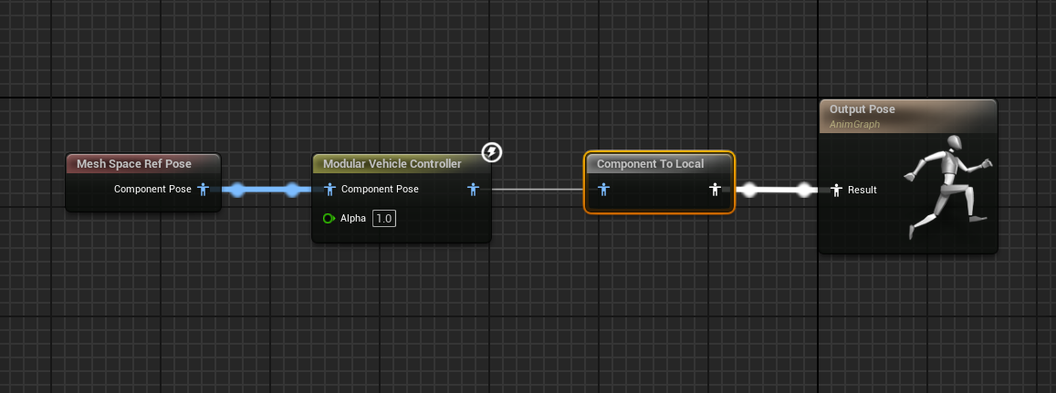
Open the animation blueprint and create a Modular Vehicle Controller node and connect it up as shown in the following image.
- Add your vehicle skeletal mesh to the vehicle Blueprint.
- On your skeletal mesh component, ensure the animation mode is set to Use Animation Blueprint, and set the Animation Class to your newly-created animation blueprint.
-
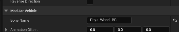
In each of the modular vehicle simulation components (wheels and suspension), enter the Bone Name for the bone you wish to animate in the skeleton mesh.
Create a ModularVehicleGameMode Blueprint
If you want to spawn the vehicle instead of a character when you start a game then you will need to create a vehicle game mode and assign this in the world settings.
- In the Content Browser, click Add (+) > Blueprint Class.
- In the Pick Parent Class window, click Game Mode Base.
- In the Content Browser, double-click to open the new Game Mode Blueprint in the Blueprint Editor.
- In the Details panel under Classes, set the Default Pawn Class to your vehicle Blueprint.
- Click Save and then close the window.
- In the Main Toolbar window, click Settings > World Settings
- In the World Settings panel, under Game Mode, set the GameMode Override to your Game Mode Blueprint.
Modules Overview
Simulation Modules Overview
| Module | Forces | Control Inputs Used | Animation |
|---|---|---|---|
| Wheel | Longitudinal and lateral grip forces can be driven or non-driven. | Uses the Steering input if they have steering enabled, the Brake input, and the Handbrake input. A normal vehicle will have steering enabled on the front wheels only however there is nothing stopping you from mixing this up. It is possible to reverse the steering input direction by defining a negative max steering angle, for rear wheel steering. | Wheels will automatically steer using the Steering input angle. Wheel rotation is also animated automatically. |
| Suspension | Suspending force generally on the Z axis. Ray traces are used to find the ground, which informs the suspension constraint of the hit point and suspension length. | N/A | Wheel travel along the suspension direction is animated automatically. |
| Engine | Provides torque for wheels. A torque curve can be defined here. | Uses the Throttle input. | N/A |
| Transmission | Connects to the engine or the clutch module. Gears and gear radios are defined here. | Uses the ChangeUp input and ChangeDown input. | N/A |
| Clutch | Connects between the engine and the transmission modules. | Uses the Clutch input. | N/A |
| Thruster | A propelling force. | Uses the Throttle and Steering inputs. | Uses the Throttle input to scale force and can be steered using the Steering input |
| Aerofoil | Lift and drag forces are generated using realistic behavior. Can be used to create an entire flying model with wings, elevator and rudder. | Uses the Roll, Pitch, or Yaw inputs depending on whether it is defined as a wing aileron, an elevator, or a rudder. | The part will rotate depending on the control surface type. The animation can be disabled, reversed, or magnified relative to the actual simulated values. |
Example Vehicles
Here are some examples of vehicles that could be created using the simulation modules:
- Traditional Automobile: Engine, Clutch, Transmission, Wheel, Suspension
- Unpowered Trolly: Wheel, Suspension
- Simple Arcade Vehicle: Thruster, Wheel, Suspension
- Aircraft: Thruster, Aerofoil, Wheel, Suspension
- Hovercraft: Suspension, Thruster, Aerofoil. (A suspension without wheels acts just like a hovercraft skirt, and an aerofoil could act as a rudder.)
Module Setup Parameters
The following tables describe the setup parameters of each of the simulation modules.
Wheel Setup Parameters
| Name | Description |
|---|---|
| Radius | The wheel radius in cm. If this is setup incorrectly, the wheels will look like they are hovering above the ground or embedded into the ground. |
| Width | Not currently used. |
| Inertia | How quickly the wheels spin up or down. |
| FrictionMultiplier | Multiplies the ground material friction to give less or more grip. A value of 1.0 is neutral. |
| CorneringStiffness | How much lateral forces the wheel generates when cornering. |
| SlipAngleLimit | The angle in degrees at which the tire starts losing grip. |
| Max Brake Torque | The maximum braking torque that will be used when the braking input is at its maximum value of 1.0. |
| Handbrake Enabled | When enabled, the wheel will react to the Handbrake input. |
| Handbrake Torque | The maximum handbrake torque that will be used when the braking input is at its maximum value of 1.0. |
| Steering Enabled | When enabled, the wheel will react to the Steering input. |
| Max Steering Angle | The maximum steering lock in degrees. A negative value will cause the wheel to steer in the opposite direction. Can be used to employ 4-wheel steering, where the front wheels use positive values and the rear wheels use negative values. |
| ABS Enabled | When enabled, the wheel will not skid under heavy braking, no matter how high the Max Brake Torque is. |
| Traction Control Enabled | When enabled, the wheel will not slip or spin under acceleration, no matter how high the Max Brake Torque is. |
| LateralSlipGraph | The cornering stiffness graph. Not yet exposed to the component. |
| LateralSlipGraphMultiplier | Easy scaling of the LateralSlipGraph output. Not yet exposed to the component. |
| Max Rotational Velocity | Limits the wheels maximum spin speed. Not yet exposed to the component. |
| Axis | Defines whether the forces are acting on the model's X axis or Y axis. Matters if the original GC component has been rotated into position. |
| Reverse Direction | Lets you reverse the direction of the forces if they are being applied in the wrong direction. Matters if the original GC component has been rotated into position. |
Suspension Setup Parameters
| Name | Description |
|---|---|
| Axis | The direction of suspension travel. |
| Offset | Offsets the location of suspension forces. |
| Max Raise | The distance in cm that the suspension will compress above the initial position. |
| Max Drop | The distance in cm that the suspension will drop below the initial position. |
| Spring Rate | The standard spring rate. |
| Spring Preload | The constant force applied when the suspension is active. Allows for lesser spring rates while still keeping the vehicle mass suspended. |
| Spring Damping | Stops the vehicle from oscillating around the neutral position. The higher the damping, the less the vehicle oscillates. |
Engine Setup Parameters
| Name | Description |
|---|---|
| Max Torque | The maximum Torque value. |
| Torque Curve | The normalized torque curve, defining torque against RPM. |
| Max RPM | The maximum RPM (revolutions per minute) the engine can achieve. |
| Idle RPM | The idling RPM, when the vehicle is sitting with no throttle depressed. |
| Engine Braking Effect | How much the engine slows the vehicle down when the throttle is released. |
| Engine Inertia | How fast the engine revs up to speed. |
| EnableBoostCapability | When enabled, the engine can activate a boost. |
| BoostMultiplier | How much the engine torque is multiplied by when the boost is active. |
Transmission Setup Parameters
| Name | Description |
|---|---|
| Transmission Type | Whether gears are set manually or automatically. The default is automatic. |
| Final Drive Ratio | Multiplies the selected gear ratio to give final gear torque multiplying effect. Usually given alongside the regular gear ratios in vehicle specs. |
| Forward Gear Ratios | The ratios for gears 1 to n. |
| Reverse Gear Ratios | The ratios for gears -1 to -n. |
| Change Up RPM | The engine RPM at which the gears will change up in automatic transmission mode. |
| Change Down RPM | The engine RPM at which the gears will change down in automatic transmission mode. |
| Gear Change Time | The time it takes to change up or down through each of the gears. |
| Transmission Efficiency | A way of defining the frictional losses in the transmission system. Not exposed to the component. |
| Auto-Reverse | When enabled, the vehicle will reverse instead of braking when the velocity is near zero. |
Clutch Setup Parameters
| Name | Description |
|---|---|
| Clutch Strength | How abruptly the clutch matches the velocities on the two shafts. |
Thruster Setup Parameters
| Name | Description |
|---|---|
| Force Axis | The axis along which the force acts. |
| Steering Axis | The axis around which the thruster rotates, if steering is enabled. |
| Force Offset | Offsets the location where the force is applied. |
| Max Thrust Force | The maximum thrust force. |
| Steering Enabled | When enabled, the thruster's direction can be controlled. |
| Max Steering Angle | The maximum angle through which the thruster can turn. |
| Steering Force Effect | Multiplies the steering component of the force so that the forward thrust can be tuned separately from the steering. A value between 0 to 1 is expected, where 0 applies no steering effect and 1 applies the full steering effect. |
| Boost Multiplier | How much the thrust force is increased when the boost input is active. Not used yet. |
| Max Speed | The maximum speed that should be achieved. Not used yet. |
Aerofoil Setup Parameters
| Name | Description |
|---|---|
| Force Axis | The axis along which the lift force is applied. |
| Offset | Offsets the location where the force is applied. |
| Control Rotation Axis | The axis around which the control surface rotates. |
| Surface Area | The surface area of the aerofoil. Doesn’t need to be realistic or match the visual model. The larger the value, the more lift you will achieve. |
| Camber | The aerofoil shape. The larger the value, the more lift you will achieve. |
| Max Control Angle | The angle in degrees through which the control surface can turn. |
| Stall Angle | The stall angle of the aerofoil in degrees. |
| Type | Specifies whether this is a Wing, Elevator, or Rudder. Defines which control input is moving the control surface, where Wing uses the Roll input, Elevator uses the Pitch input, and Rudder uses the Yaw input. |
| Lift Multiplier | A way of cheating the calculated lift component of the aerofoil calculation, separate from the drag. The default value is 1.0. |
| Drag Multiplier | A way of cheating the calculated drag component of the aerofoil calculation, separate from the lift. The default value is 1.0. |
| Animation Magnitude Multiplier | Changes how much the part visually rotates independent of the control angle. The part will be animated to an angle equal to the control angle multiplied by this value. |