
AppendVector
The AppendVector expression enables you to combine data channels together to create a vector with more channels than the original. For example, you can take two individual Constant values and append them to make a two-channel Constant2Vector value. AppendVector is also useful for reordering the channels within a single texture or for combining multiple grayscale textures into one RGB color texture.
| Input | Description |
|---|---|
| A | Takes the value(s) to append additional data to. |
| B | Takes in the value(s) that will be appended to A. |
Example
AppendVector works in order of input, meaning the data in input B is appended to the end of the data in input A. In the example below there are two separate append operations. First 0.2 and 0.4 are appended together, resulting in a two-channel vector (0.2, 0.4). In the second Append node, a constant value of 1 is appended to the end of (0.2, 0.4). The final result is a three-channel vector (0.2, 0.4, 1). In this example it is used as an RGB value to define the base color of the Material.

ComponentMask
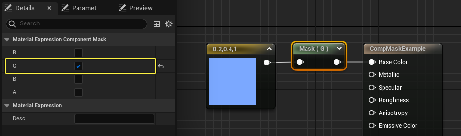
The ComponentMask expression enables you to select a specific subset of channels (R, G, B, and/or A) from the input to pass through to the output. Attempting to pass a channel through that does not exist in the input will cause an error, unless the input is a single constant value. In that case, the single value is passed through to each channel. The current channels selected to be passed through are displayed in the title bar of the expression.
Select the ComponentMask expression in the Material Graph, and use the check-boxes in the Details Panel properties to choose which channels are allowed to pass through to the output.
| Property | Description |
|---|---|
| R | If checked, the red (first) channel of the input value is passed through to the output. |
| G | If checked, the green (second) channel of the input value is passed through to the output. |
| B | If checked, the blue (third) channel of the input value is passed through to the output. |
| A | If checked, the alpha (fourth) channel of the input value is passed through to the output. |
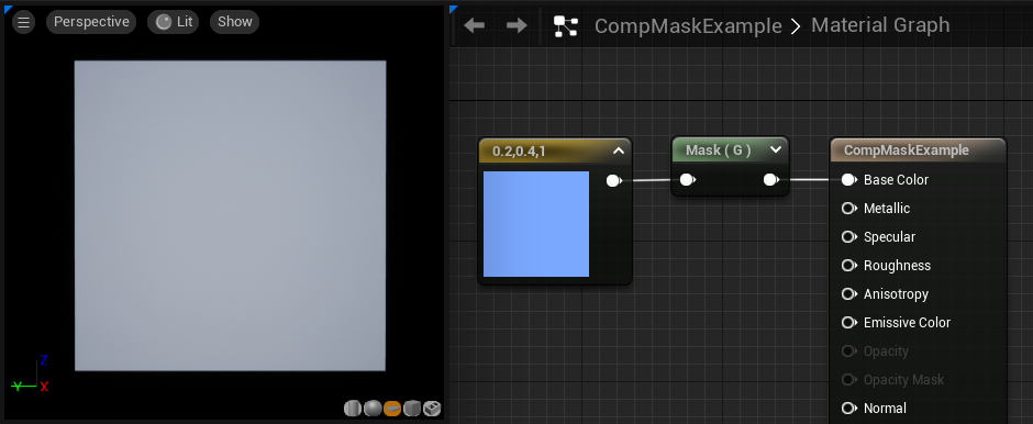
The example below shows a ComponentMask with an input of (0.2,0.4,1.0). Only the G channel is enabled in the details panel, so the node outputs a value of 0.4. This appears as a 40% bright grayscale value when passed into the Material's Base Color input.
CrossProduct
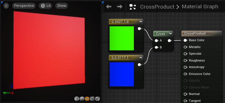
The CrossProduct expression computes the cross product of two three-channel vector value inputs and outputs the resulting three-channel vector value. Given two vectors in space, the cross product is a vector that is perpendicular to both of the inputs.
| Input | Description |
|---|---|
| A | Takes in a three-channel vector value. |
| B | Takes in a three-channel vector value. |
Example Usage: CrossProduct is often used to compute directions which are perpendicular to two other directions.
DeriveNormalZ
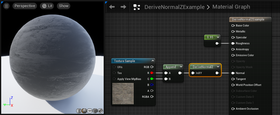
The DeriveNormalZ Expression derives the Z component of a tangent space normal given the X and Y components, and outputs the resulting three-channel tangent space normal. Z is calculated as Z = sqrt(1 - (x * x + y * y));
| Input | Description |
|---|---|
| InXY | Takes in the X and Y components of the tangent space normal in the form of a two-channel vector value. |
DotProduct
The DotProduct expression computes the dot product, which can be described as the length of one vector projected onto the other, or as the cosine between the two vectors multiplied by their magnitudes. This calculation is used by many techniques for computing falloff. DotProduct requires both vector inputs to have the same number of channels.
| Input | Description |
|---|---|
| A | Takes in a value or vector of any length. |
| B | Takes in a value or vector of the same length as A. |

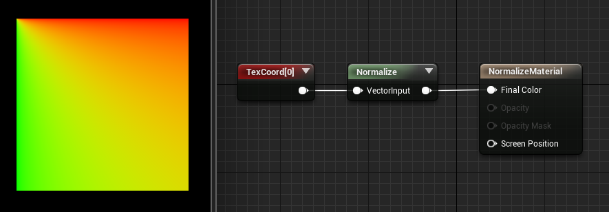
Normalize
The Normalize expression calculates and outputs the normalized value of its input. Normalized vectors (also called "unit vectors") have an overall length of 1.0. This means each component of the input is divided by the total magnitude (length) of the vector.
Examples: Passing either (0,2,0) or (0,0.2,0) through Normalize will output (0,1,0). Passing (0,1,-1) through Normalize will output (0, 0.707, -0.707). The only special case is an all-zero vector, which will be unchanged.

It is not necessary to normalize an expression that plugs into the Normal material output.
Transform
The Transform Material Expression converts a three-channel vector value from one reference coordinate system to another.
By default, all shader calculations in a Material are done in tangent space. The vector constants, camera vector, light vector, and so on are all transformed to tangent space before being used in a Material. The Transform expression allows you to transform these vectors from tangent space to the world-space, local-space, or view-space coordinate systems. Additionally, it enables world-space and local-space vectors to be transformed to any of the other reference coordinate systems.
When the Transform node is selected in the Material Graph, the following properties display in the details panel.
| Property | Description |
|---|---|
| Source | Specifies the current coordinate system to transform the vector from. This can be one of: World, Local, or Tangent. |
| Destination | Specifies the target coordinate system to transform the vector to. This can be one of: World, View, Local, or Tangent. |
The Transform node accounts for mirrored UVs, thus allowing, for example, highlights that only affect the right edge of a character.
The Transform node is useful for generating world space normals for sampling a cubemap. A normal map can be transformed to world space. Below is an example of transforming normals from tangent space to world space in order to sample a cubemap.
Click image for full size.
Transforming normals to view space is useful for creating edge-on effects. This can be achieved by using mesh normals to generate texture coordinates (commonly referred to as "Sphere Mapping"). With this method, normals facing directly at the camera will map to the center of the texture coordinates, and normals facing perpendicular to the camera will map at the edge of the texture coordinates. For example, you could use the Transform expression to map a bullseye texture so that it always faces the camera.

A Constant3vector with a value of (0,0,1) is fed into the Transform node set to Tangent Space to View Space. This is then passed through a ComponentMask (passing only R and G). Since the Transform will output a range of values from -1 to 1, we bias the values to put them into the 0-1 range. This is done by multiplying by 0.5, and then adding 0.5. Then simply plug that into the Coordinates of the bullseye texture.
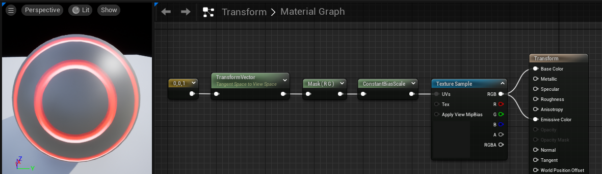
When orbiting around the static mesh, the bullseye always remains centered in view space. By changing the Destination property in the Transform node to World Space instead of View Space, you can project the texture along the Z-axis instead.
VertexColor is mutually exclusive with the Transform node due to limited interpolators. If you use both a Transform node and VertexColor, then VertexColor will come out all white.
The transform node currently does not handle non-uniform scaling correctly.
TransformPosition
The TransformPosition expression can transform any position from screen space to the destination space specified by the expression's TransformType variable. Currently only transforming into world space is supported. This expression can be used to get world space coordinates in the material. To visualize world position, you can plug it straight into emissive: