
Pose Warping lets you dynamically adjust a character's animated pose to align with Capsule Movement. This document will describe the Pose Warping features as well as demonstrate an implementation of Pose Warping in your Character's Animation Blueprint.
Prerequisites
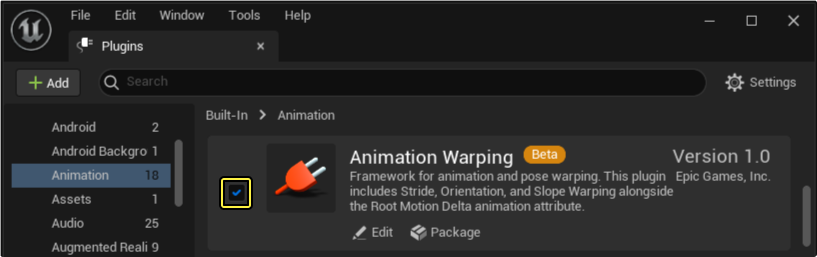
- Enable the Animation Warping plugin. For more information regarding Plugins and how to Install them, refer to Working With Plugins.
-
Pose Warping uses Animation Blueprint workflows, so you need to understand this feature.
-
In addition, a Root Motion enabled animation, an Implemented IK Rig, and a Direction Variable driven by Root Motion, must be accessible in the project where you want to create gameplay examples.
Pose Warping Overview
The Pose Warping set of Animation Blueprint nodes perform dynamic adjustments to Animation Sequence Poses through warping, to create more cohesive animation interactions within the game world.
Pose Warping can be broken down into three nodes. Each of these nodes performs a specific-use warping implementation to adjust animations to match Root Motion in unique ways.
Within the properties of each node, many parameters can be defined through a Manual Evaluation mode of control over the generation of these warps. A Graph Evaluation mode is also present and can define these parameters automatically.
General Details
Below you will find an explanation of the Pose Warping node properties and their functions.
| Name | Description |
|---|---|
| Mode | Select a mode in which the Pose Warping node will derive the value with which to Warp the Poses of animation. Manual: Animation Warping evaluations are derived from the user-defined parameters. Due to a lack of transitional smoothness when relying on updating variables, this is best used in static or scripted instances. Graph: Animation Warping evaluations are derived from dynamically-defined, graph-driven parameters. Some node properties will change and now require Root Motion enabled Animation Sequences. |
| IK Foot Root Bone | Define the IK Foot Root Bone of the skeleton. |
Pose Warping Nodes
Below you will find a description of the unique properties for each of the Pose Warping nodes, and explanations of their functions.
Orientation Warping
The Orientation Warping node applies directional compensation warps to animations in motion. With this node, you can isolate and warp the leg IK bones of an animation pose to align with the dynamically updating locomotion direction of the root motion. The pose will also maintain the facing angle by twisting the spine bones along a designated axis.
This feature can be used to fill coverage gaps in animation sequences, reducing the need to manually create interstitial animations or the creation of excess blend space transitions.
Below you will find a description of the Orientation Warping properties and their functions.
| Property | Description |
|---|---|
| Orientation Angle | Only available when the Evaluation Mode property is set to Manual. Defines the degree of orientation you want to warp the locomotion component's pose. This value is relative to the Axis specified under the Rotation Axis property. |
| Locomotion Angle | Only available when the Evaluation Mode is set to Graph. Defines the degree of orientation you want to warp the locomotion component's pose. Built to use graph-driven values, the Locomotion Angle excels with dynamically changing values. This will be used in the following equation for computing the orientation angle: [Orientation = RotationBetween(RootMotionDirection, LocomotionDirection)]. |
| Location Angle Delta Threshold | Specifies an angle threshold to prevent erroneous over-rotation of the character. By default, this property is set to 90 degrees, and it can be disabled by setting a value of 0. |
| Spine Bones | Defines the spine bones which taper the warp throughout, to provide a more seamless-looking rotation. Use the Add (+) button to add more definitions. Index 0 is the highest hierarchically-ranked and the least-rotated bone, with each additional Index being the next nested spine bone and more progressively influenced by the rotation. |
| IK Foot Bones | Add and define the Index instances of the IK Foot Bones present in the skeleton. |
| Rotation Axis | Define the axis by which the orientation warp should occur. For most cases, orientation warping should occur on the Z axis, resulting in a twisting of the body. |
| Distributed Bone Orientation Alpha | Specifies how much of the rotation is distributed across the character body through the spine bones. This value is biased towards the upper body, with a value of 1 indicating that the total rotation occurs at the Index 0 spine bone and a value of 0 indicating rotation occurs at the highest indexed spine bone. |
| Rotation Interp Speed | Specifies the interpolation or blending speed (in alpha per second) in order to reach the final warped rotation angle. Lower values indicate low interpolation speed and thus slow transitions between locomotion changes and animation warping. Greater values will have quicker transitions with less smoothing. A value of 0 will cause instantaneous rotation. |
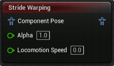
Stride Warping
Stride Warping is a Pose Warping node that dynamically adjusts the animated stride of a character to match the capsule movement speed. By defining the speed of motion, and the relevant bones, the Stride Warping node is able to modify the spacing between foot positions, to create a dynamically adjusting stride length to match motion speed. This reduces the need to manually tune movement speeds to match animation playback, and reduces the dependency on blend spaces to transition between different animation sequences for different speeds of movement.
Below will find the Stride Warping properties and their applications.
| Property | Description |
|---|---|
| Stride Direction | Only available if the Evaluation Mode is set to Manual. Defines the direction of motion towards which the stride will be. |
| Stride Scale | When the Evaluation Mode is set to Manual, scales the amount of warping applied to the foot definitions in order to fine tune the stride adjustment. A value of 1 will provide a default scale of warping, 0.5 will decrease the effective leg stride by half, and a value of 2 will double the effective leg stride. The following equation will be used for computing the Stride Scale: [StrideScale = (LocomotionSpeed / RootMotionSpeed)]. |
| Locomotion Speed | When the Evaluation Mode is set to Graph, specifies the current speed of motion applied to the character. Relying on the Graph Driven Evaluation mode, this parameter is designed to work cohesively with dynamically updating data, such as Root Motion or Capsule speed. For best results, the declared speed should be relative to the delta time of the animation graph. |
| Min Locomotion Speed Threshold | The defined threshold for the minimum locomotion speed value required to apply the effects of the Stride Warping feature. |
| Pelvis Bone | Define the skeleton's Pelvis Bone. |
| Foot Definitions | Within this parameter, Indexes can be created and used to define the necessary IK and FK feet and thigh bones to perform warps. One index with its necessary definitions is needed per locomotion leg present in the skeleton. |
| Stride Scale Modifier | With this parameter, you can add clamps and interpolation guidelines that will modify the final Stride Scale Result. These limits can be activated by toggling the Clamp Result or the Interp Result sub-properties. Clamps can be modified by specifying the minimum and maximum values to allow scaling to take place. A value of 1 is the base scale, 0.5 is half scale, and 2 is double scale. Interpolation speeds can be defined to control the range at what motion speeds the interpolation is applied. Interp Speed Increasing defines the threshold at which interpolation is applied with increasing motion speed values. Inversely, Interp Speed Decreasing defines the threshold at which interpolation is applied as motion speed is decreasing. |
Below you will find the Advanced properties found in the parameters of the Stride Warping node used for fine tuning stride warping applications.
| Name | Description |
|---|---|
| Floor Normal Direction | This value internally converts into a corresponding Component-space representation prior to warping. Mode: Space of the corresponding Vector Value. Component Space Vector Actor Space Vector World Space Vector IKFoot Root Local Space Vector Value: Specifies a vector relative to the space defined by Mode. |
| Gravity Direction | This value internally converts into the corresponding Component-space representation prior to warping. Declares the space to which this property will convert the corresponding Vector Value that will apply the simulated directional pull of gravity. The different modes of declared space are as follows: Component Space Vector Actor Space Vector World Space Vector IKFoot Root Local Space Vector |
| Pelvis IK Foot Solver | Solver for controlling how much the pelvis is "pulled-down: towards the IK/FK foot definitions during leg limb extensions. Pelvis Adjustment Interp: Specifies the spring interpolation parameters applied during pelvis adjustment. Defined by a Stiffness Constraint property and Dampening Ratio Property. Pelvis Adjustment Interp Alpha: Specifies an alpha between the original and final adjusted pelvis locations. This is used to retain some degree of the original pelvis motion. Pelvis Adjustment Max Distance: Specifies the maximum displacement the pelvis can be adjusted relative to its original location. Pelvis Adjustment Error Tolerance: Specifies that if the pelvis adjustment distance is incrementing at a value lower or equal to this value for each iteration, the solve will halt. Lower values will marginally increase visual quality at the cost of performance, but may require a higher PelvisAdjustmentMaxIter to be specified. Pelvis Adjustment Max Iter: Specifies the maximum number of iterations to run for the pelvis adjustment solver. Higher Iterations will guarantee closer PelvisAdjustmentErrorTolerance convergence at the cost of performance. |
| Orient Stride Direction Using Floor Normal | Orients the specified (Manual) or computed (Graph) stride direction by the floor normal. |
| Compensate IK Using FK Thigh Rotation | Include warping adjustments to the FK thigh bones alongside the IK/FK foot definitions. This is used to help preserve the original overall leg shape. |
| Clamp IK Using FK Limits | Clamps the IK foot warping to prevent over-extension relative to the overall FK leg. |
Slope Warping
Slope Warping assists in warping feet locations to match the floor normals, to create smoother transitions of locomotion animations on inclines and stairs.
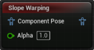
This node is still in development, don't trust a project to its functionality, but implementation is encouraged in testing environments.
Below is a list of properties associated with the Slope Warping node.
| Name | Description |
|---|---|
| Pelvis Bone | Define the skeleton's Pelvis Bone. |
| Feet Definitions | Within this parameter, Indexes can be created and used to define the necessary IK and FK feet bones, the Number of Bones associated to the defined feet, and the Foot Size value, in Unreal units. These definitions define the bones the node will use to perform the slope warps. You need one index with its necessary definitions per locomotion leg present in the skeleton. |
| Pelvis Offset Interpolator | Specifies the pelvis bone offset interpolation parameters applied during pelvis adjustment. Defined by a Stiffness Constraint property and Dampening Ratio property. |
| Gravity Dir | Define the Direction of gravitational pull in the skeletal elements affected by the warp. |
| Custom Floor Offset | Define which axis to use to perform the custom floor offset in relation to the skeleton. |
| Floor Normal Interpolator | Specifies the floor normal interpolation parameters applied during pelvis adjustment. Defined by a Stiffness Constraint property and Dampening Ratio property. |
| Floor Offset Interpolator | Specifies the floor offset interpolation parameters applied during pelvis adjustment. Defined by a Stiffness Constraint property and Dampening Ratio property. |
| Max Step Height | Defines the maximum value of height adjustment possible between steps of slope warping in Unreal units. |
| Keep Mesh Inside Of Capsule | When enabled, prevents warping from pushing the Mesh outside of the Capsule. |
| Pull Pelvis Down | Enables pulling the pelvis down to accommodate new foot placements. |
| Use Custom Floor Offset | Toggles the use of a custom floor offset. |
Pose Warping Workflow
The workflow below demonstrates a basic implementation of the Orientation Warp node in a Character's Animation Blueprint to add warping to locomotion animations.
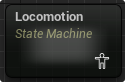
To begin, call a reference to a Root Motion Enabled Animation Sequence, within the AnimGraph of a character's Animation Blueprint. For this demonstration, the animation can be as simple as a single directional movement animation, and as complex as a full array of cardinal direction movements with transitions. The Locomotion State Machine used in this demonstration, only contains a forward jog animation.
With this single animation, and the Orientation Warping node, a full 180 degrees of lower body animation will be possible, adapting to analog input controls while retaining the upper body facing angles.
Adding Necessary AnimBP Nodes
This demonstration uses a simple state machine with a transition between an idle and single forward jog animation that is Root Motion Enabled.
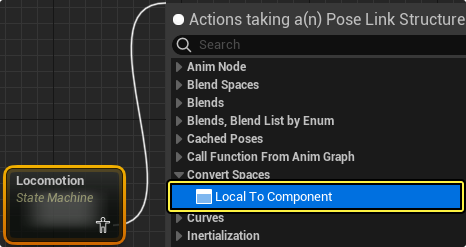
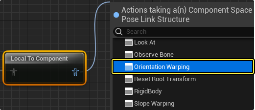
By dragging off of the Output Pin of the State Machine, create a Local To Component space conversion node. This node is required to convert the animation poses that make up the animation sequence to the component space.
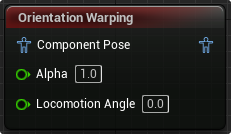
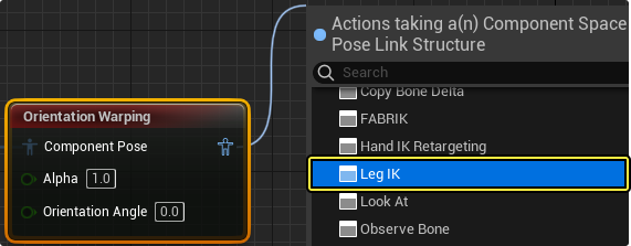
From this Local To Component space conversion node, drag off of the Output Pin to create the Orientation Warping node.
After the Orientation Warping node, you need a downstream Leg IK node to communicate the warps being made to the IK bones of the skeleton to the FK bones.
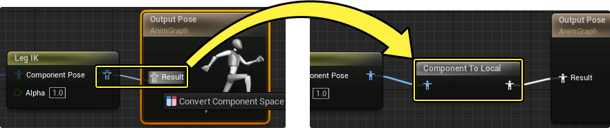
By connecting the Leg IK node to the Result node, the Local to Component conversion will close automatically by creating a Component To Local space conversion node.
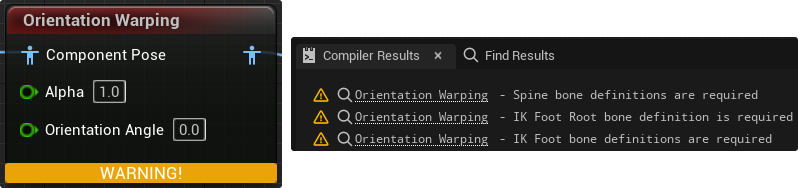
With all of the necessary nodes in place, compiling will return errors related to the Orientation Warping node. Within the compiler results panel, the Orientation errors listed request spine and IK bone definitions. These bones can be defined in the Orientation Wrapping properties found in the details panel, and are explained in the next section.
Defining Necessary Parameters
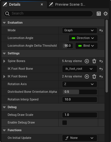
Clicking the Orientation Warping node in the AnimGraph viewport will open the Details panel. Under the Settings header, you can assign the instances of the IK foot root and the individual IK feet for the skeleton. Additionally you will need to Add (+) and specify at least one spine bone for the node to displace the twist in order to retain the facing angle of the character. One bone will operate like a pivot point for the entire lower body. Adding more spine variables will taper the warp across the spine bones to appear more natural.
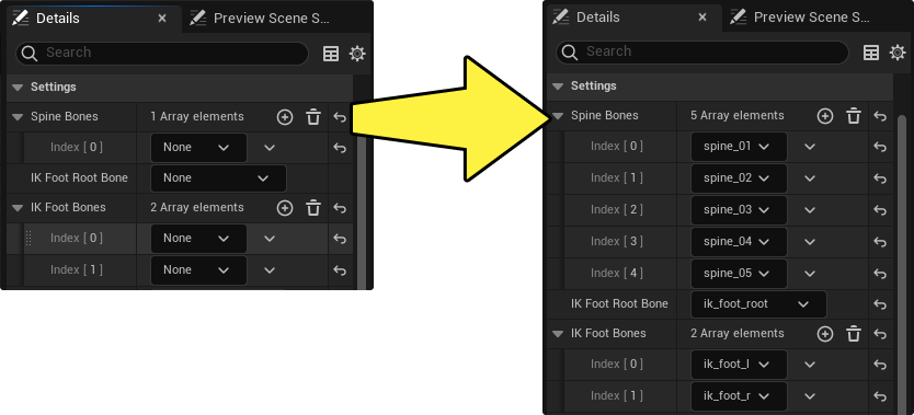
It is a good idea to populate as many spine bones as are present in the skeleton of your model.
Now the Orientation Warping angle must be defined. This angle can be defined manually with extensive parameterization, or a dynamic value, such as a directional variable driven by the angle of Root Motion, can provide this angle automatically.
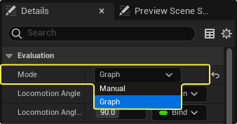
In the Details panel of the Orientation Warping node, change the Evaluation Mode to Graph. The Graph Evaluation mode will change the Orientation Angle pin, a manual and static value, to the Locomotion Angle pin which can be connected with a graph-driven value. For this example we will use a Direction variable driven by the Capsule movement direction.
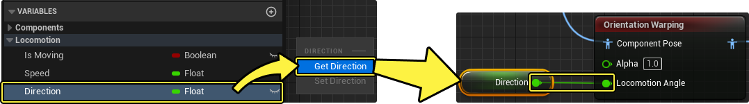
Call the Direction variable and connect the Output Pin of the variable node to the Locomotion Angle Input Pin.
Lastly, you need definitions for the IK bones with their FK bone counterparts within the IK Rig properties to blend the occurring warps.
In the IK Rig Details panel, create a Leg Definition array for each leg present in the model using Add (+). Define the IKFoot Bone and the FKFoot Bone in the array.
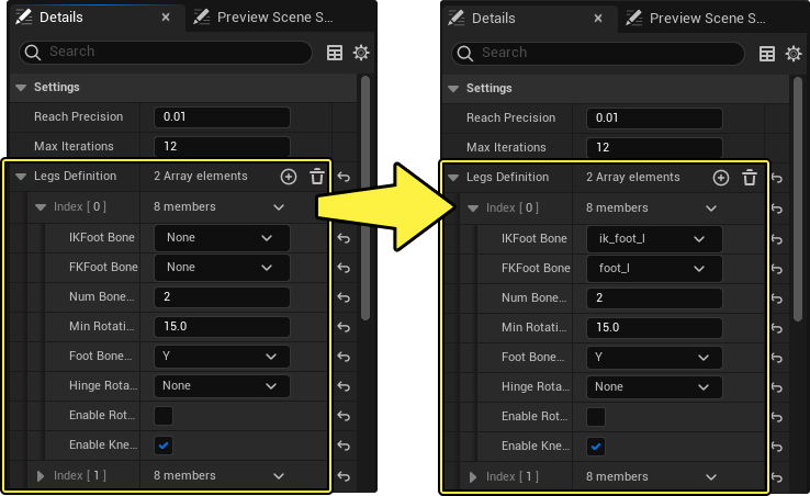
The Num Bones In Limb property, found in the Leg Definition array, describes the number of bones found in the leg structure that are associated with each foot. This value, not including the foot bones themselves, must account for every bone that makes up the remaining structure that should be warped. In the case of this example, from the foot we have a calf and a thigh bone before reaching the pelvis bone. Since the pelvis is not a part of the leg structure, we declare 2 bones to associate with the already defined foot bone. This is a typical structure but your skeletal mesh may differ.
Results
Compiling, saving, and playing the level demonstrates effects of the Orientation Warping node. With only a single animation sequence, a forward jogging animation, a full 180 degrees of locomotion coverage is generated. In addition, by defining the spine bones, a facing angle is retained so the character remains facing the direction of movement.
| Before Pose Warping | After Pose Warping |
|---|---|
 |
 |
| In the above demonstration, the input being applied to the character does enact locational and direction movement to the mesh, through the capsule. Due to the limitations of the present animation coverage, the input has no effect on the animation playback. The animation simply loops in a single direction. | After the above workflow is completed, warping is being performed in real-time, driven by the character's input. Notice the twisting occurring in the spine, in order to focus the direction of the leg animation to follow the input-driven locomotion direction (Red arrow), while also retaining the Root Motion driven facing direction (Blue Arrow). |
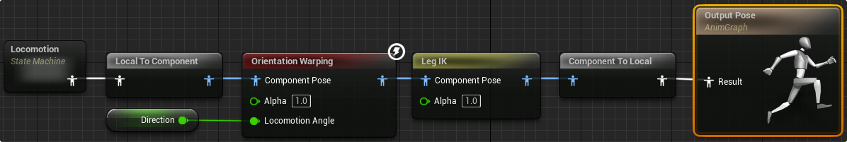
Below is a full image of the Animation Blueprint logic used for this page's implementation of the Orientation Warping node.
Debugging
Below you will find a description of debugging properties to assist in correcting any encountered issues when implementing the Orientation or Stride Warping nodes.
Orientation Warping
Below you will find a description of the Orientation Warping node's Debugging properties and a description of their function.
| Name | Description |
|---|---|
| Debug Draw Scale | Uniformly scales the visually drawn debugging guides. |
| Enable Debug Draw | If enabled, a set of colored arrows will be drawn to represent vectors of interest, originating from the character in the viewport during run. Red arrow: Input Direction. Blue arrow: Root Motion. Green arrow: Simulated Direction, a blended vector, determined by input and displayed action. The speed of this blending can be adjusted using the Rotation Interp Speed property in the Details panel. |
Stride Warping
Below is a list of Debugging properties to assist in the successful implementation of the Stride Warping node.
| Name | Description |
|---|---|
| Debug Draw Scale | Uniformly scales the visually drawn debugging guides. |
| Enable Debug Draw | Displays a red arrow, representing a movement speed vector, originating from the center of the Character's Capsule, in the viewport during run. With a higher input force, a longer arrow will be drawn, and with smaller input force, the arrow will shorten. |
| Debug Draw IKFoot Origin | When enabled, the defined IK Feet are made visible with a red sphere. |
| Debug Draw IKFoot Adjustment | If enabled, blue vector arrows will be drawn, originating from the IK Feet center, to visibly show the adjustments being made. |
| Debug Draw Pelvis Adjustment | When enabled, a vector will be drawn in the viewport, indicating the Pelvis Bone adjustments being made. |
| Debug Draw Thigh Adjustment | Toggle drawn vectors to visually see adjustments being made to the defined Thigh Bones. |
| Debug Draw IKFoot Final | This property will enable drawing a visual representation of the final location of IK Feet bones after a full warp has occurred. |