
The individual assets that make up a vehicle are as follows.
- A Skeletal Mesh
- A Physics Asset
- An Animation Blueprint
- A Vehicle Blueprint
- One or more Wheel Blueprints
- A Float Curve asset that represents the engine's torque curve
These are the same no matter whether you are creating an automobile or a motorcycle. This document will guide you through the process of setting up a Vehicle.
-
Enabling the Chaos Vehicles Plugin.
-
Creating and Editing Chaos Wheel Blueprints.
-
Creating a Curve Asset for the engine torque.
-
Importing a Vehicle Mesh.
-
Creating and Editing a Physics Asset.
-
Creating an Animation Blueprint with the Wheel Controller node.
-
Creating a Vehicle Blueprint.
-
Setting up Vehicle Control Inputs.
-
Setting up the Vehicle Game Mode.
Enabling the Chaos Vehicles Plugin
Before using Chaos Vehicles, the Chaos Plugin needs to be enabled.
-
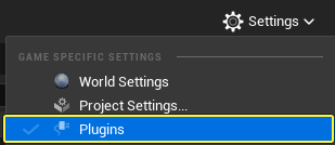
Click Settings > Plugins to open the Plugins Menu.
-
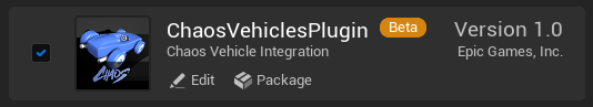
Click the Physics category and enable the ChaosVehiclesPlugin.
- Restart Unreal Editor after enabling the plugin.
- This plugin will not work with PhysX enabled.
Creating and Editing Chaos Wheel Blueprints
The wheel Blueprint is where the configuration for a Wheel / Suspension / Brakes combination is set up.
In most cases, you will require at least two wheel types per vehicle. A wheel (or axle) that is affected by the steering / engine / handbrake, and one that is not. Also, this may be the case for having differently sized wheels for the front or the back, in which case, you have full control over setting the differing radii, mass, width, handbrake effect, suspension, and many other properties to give your vehicle the handling you desire.
There is no limit on the number of wheels that a vehicle may have. It is possible for multiple vehicles to share the same Wheel Blueprints, but this strategy is only valid if the wheel dimensions and suspension limits are the same.
Create a Wheel Blueprint
-
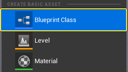
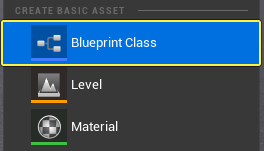
In the Content Browser, right-click and select Blueprint Class from the Create Basic Asset section.
-
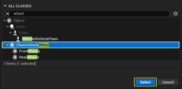
In the Pick Parent Class window, under All Classes, search for "wheel" and select ChaosVehicleWheel. Click Select to create the asset.
-
The new asset will be created in the Content Browser. Give it a recognizable name so that you can easily locate it later (for example, 'BP_ChaosFrontWheel').
-
(Optional Step) Repeat these steps again so that you have a front and rear wheel type. Think of each as a setup per axle.
Edit the Wheel Blueprint
Double-click the assets in the Content Browser to open them in the Blueprint Editor, where there are options to edit the wheels.
To start, there are five properties that need to change for each wheel, as the rest of the properties depend on how the vehicle performs (and should be tweaked later on) during testing.
| Property | Notes |
|---|---|
| Axel Type | This defines whether the wheel is in the front or the rear of the vehicle. |
| Wheel Radius | This needs to match the size of the render model in centimeters (cm). |
| Affected by Handbrake | Enable this in the rear wheels. |
| Affected by Engine | Enable this in the rear wheels for a rear-wheel drive (RWD) vehicle. Enable this in the front wheels for front-wheel drive (FWD) vehicles. Enable this on all of the wheels for all-wheel drive (AWD) vehicles. |
| Affected by Steering | Enable this in the front wheels. For vehicles with more wheels in the front (for example, a truck cab might have four-wheel steering), enable it in the second layer with a different steering angle. Alternatively, all-wheel steering is possible by selecting steering on the rear wheels with a negative steering angle. |
| Max Steer Angle | Normally, this is a positive value (specified in degrees). However, a negative value is allowed for rear-wheel counter-steering for all-wheel drive (AWD) vehicles. |
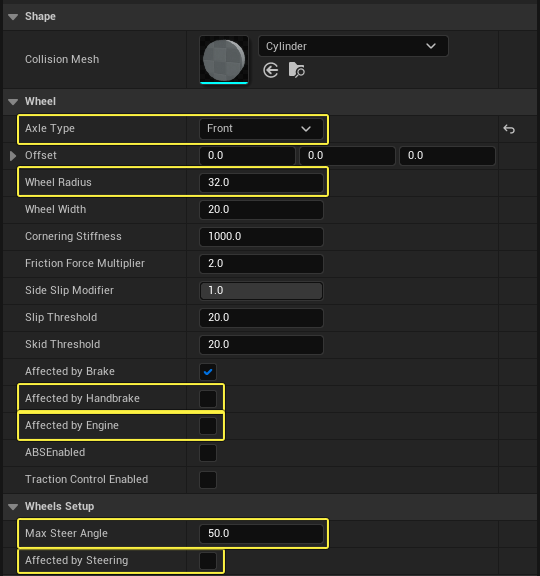
Example Class Defaults for the Chaos Wheel Blueprint.
For the buggy example, set the Wheel Radius to 58 for both front and back wheel Blueprints.
Creating a Curve Asset for the engine torque
The torque curve represents the amount of torque output from the engine at a given RPM. The graph's X axis represents the engine RPM (revolutions per minute) with a range from 0 to the engine max RPM. The Y axis represents the engine Torque output in NM (Newton Meters). A typical torque curve is an inverted U shape with the torque peaking near the middle of the rev range, and trailing off either side.
To create your torque curve, follow these steps:
-
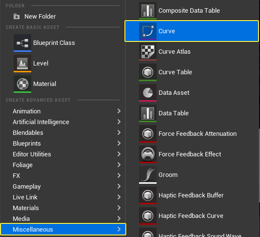
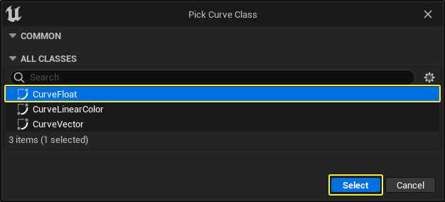
In the Content Browser, right-click and select Miscellaneous > Curve. Select the Curve Float type and click the Select button to create the asset.
-
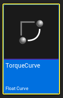
Name the asset TorqueCurve.
-
In the Content Browser, double-click TorqueCurve to open it in the Curve Editor. Add points to create the curve shape to your liking.
Importing a Vehicle Mesh
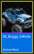
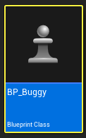
This guide uses the Buggy vehicle mesh from the Vehicle Game sample project. In the Epic Games Launcher click the Learn tab to find the project.
Vehicle Physics Editor
After importing a vehicle mesh to your project, follow these steps to view the mesh in the Physics Asset Editor.
-
In the Content Browser, double-click the vehicle Skeletal Mesh to open it.
-
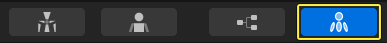
Click the Physics tab to open the Physics Asset Editor.
Creating and Editing a Physics Asset
Creating the Physics Asset
If you have a skeletal mesh that does not have an associated physics asset, then you can create a physics asset by following these steps:
-
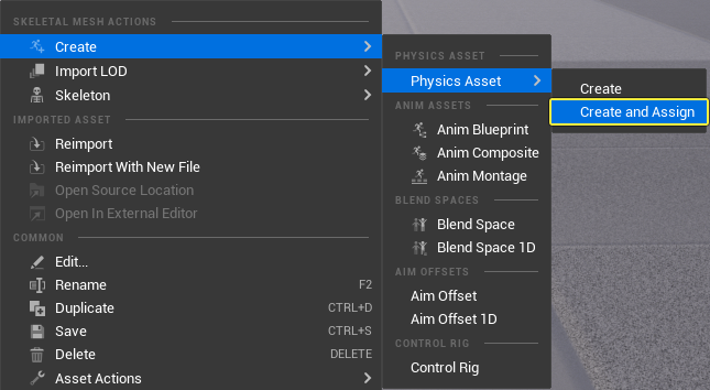
In the Content Browser, right-click the skeletal mesh asset and select Create > Physics Asset > Create and Assign.
-
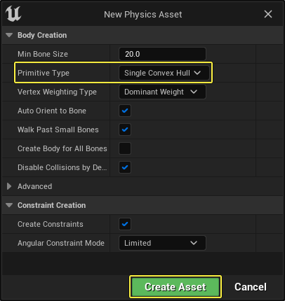
Click the Primitive Type dropdown and select Single Convex Hull. Click Create Asset to create a new physics asset.
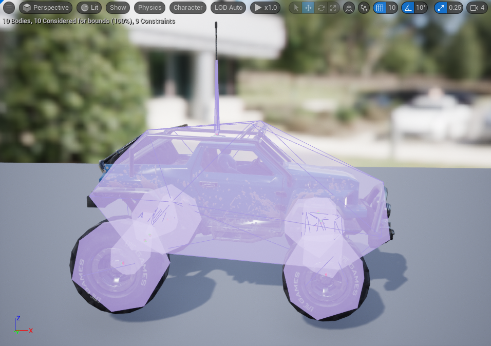
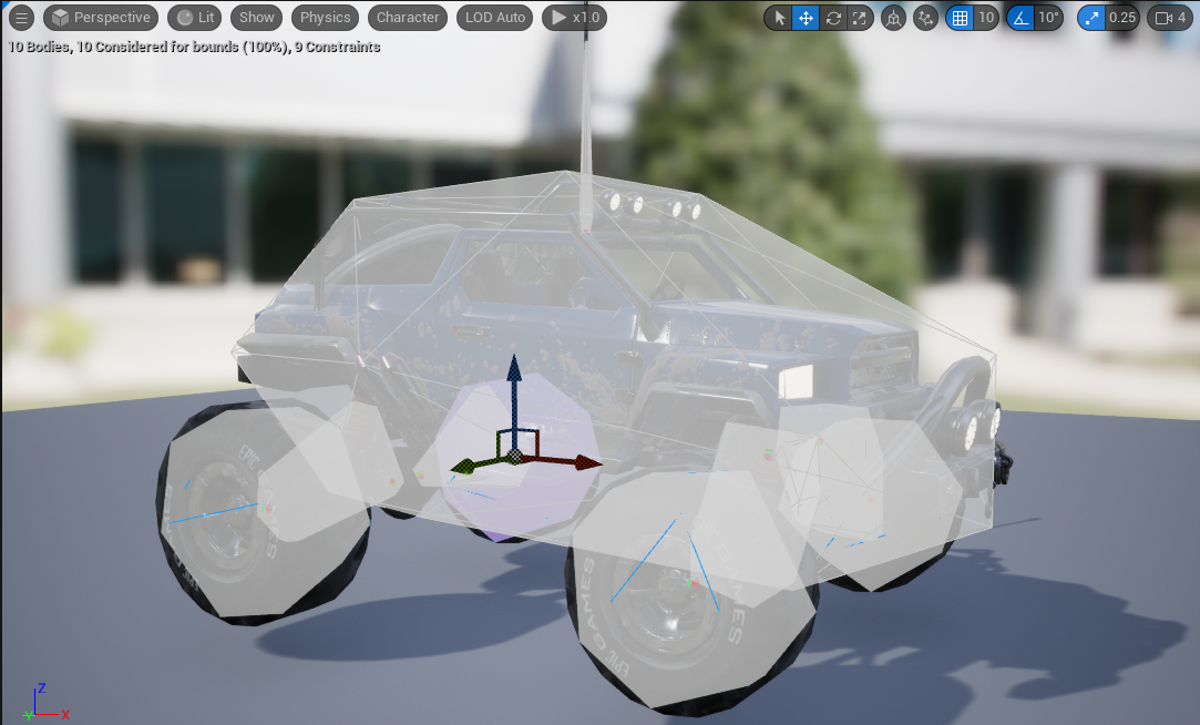
This will generate a physics asset with default collision shapes for each of the bones. The initial collision setup will most likely not be ideal since it will use the same primitive type to represent all of the bones in the physics asset.
-
In the Content Browser, right-click the physics asset to open it in the Physics Asset Editor.
-
Inside the Physics Asset Editor you can adjust the collision primitives used on each bone to better suit the vehicle mesh.
Editing the Physics Asset
-
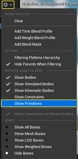
In the Skeleton Tree window, click the gear icon and select Show Primitives.
-
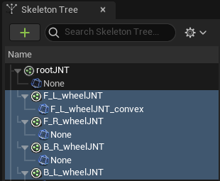
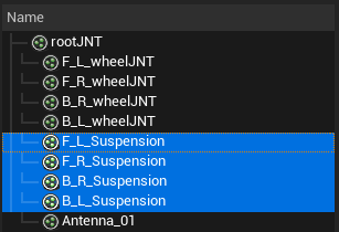
Select all the wheel bones inside the Skeleton Tree window.
-
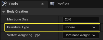
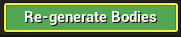
Go to the Tools window and under the Body Creation section, click the Primitive Type dropdown and select Sphere. Click Re-generate Bodies.
-
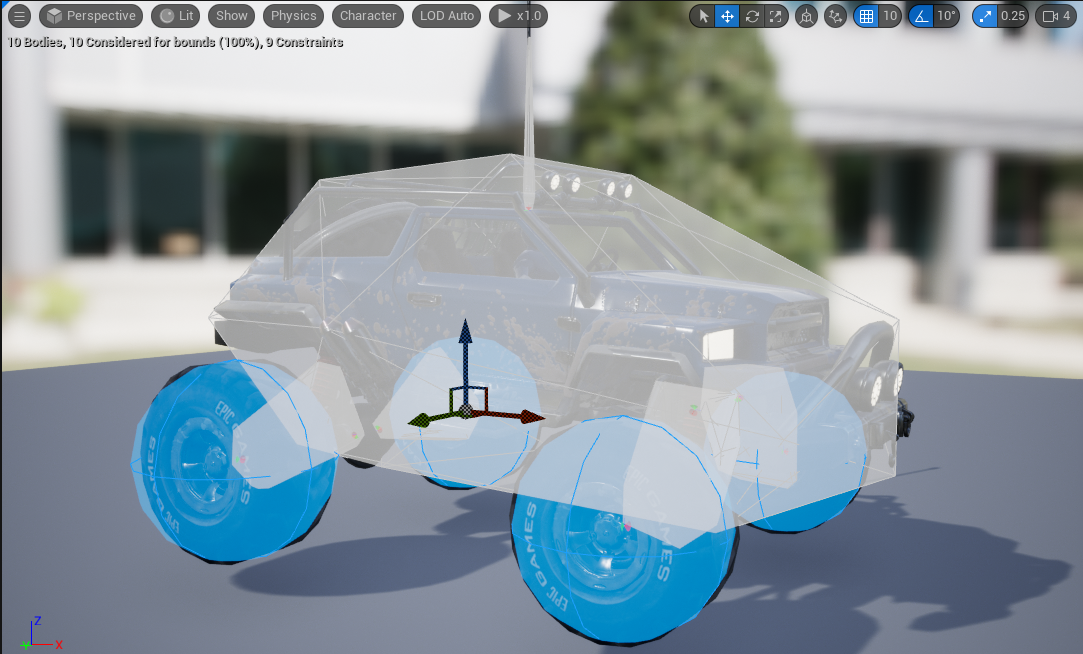
You can now see the Sphere primitives on each of the wheels.
-
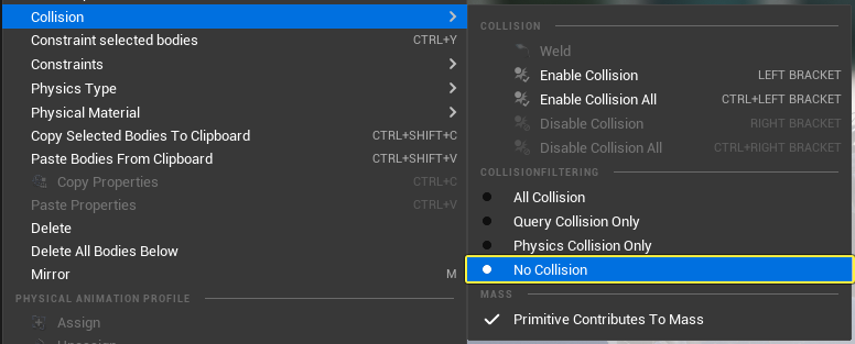
Select the suspension bones inside the Skeleton Tree window. Right-click and select Collision > No Collision to remove collision from the vehicle suspension.
Creating an Animation Blueprint with the Wheel Controller node
Animation Blueprints are used to control Vehicle Skeletal Mesh animations specific to that vehicle, such as spinning tires, suspension, handbrakes, and steering animations. To offload a lot of the work in creating these types of animations, you can use the Wheel Controller Node to drive the animations.
Wheel Controller Node
Where an Animation Blueprint is used to get and control animations for the vehicle, the Wheel Controller node makes controlling all of the animations for the vehicle straightforward with little to no additional setup.
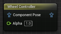
The node gets the necessary information from the wheels (such as "How fast is it spinning?" or "Is it affected by the Handbrake?" or "What are the suspension settings for this wheel?"), and translates the query results to an animation on the bone that the wheel is associated with.
Create an Animation Blueprint
-
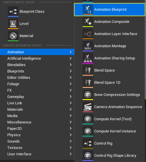
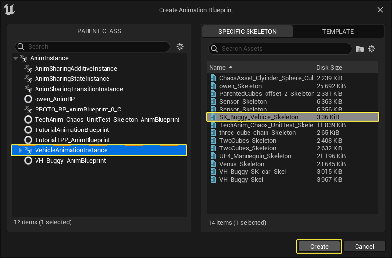
In the Content Browser, right-click and select Animation > Animation Blueprint.
-
In the Create Animation Blueprint window, select the VehicleAnimationInstance parent class and select the vehicle Skeleton from the list. Click Create to create a new Animation Blueprint asset.
-
In the Content Browser, double-click the animation Blueprint to open it.
-
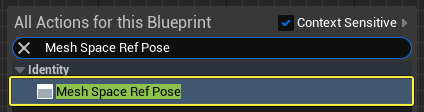
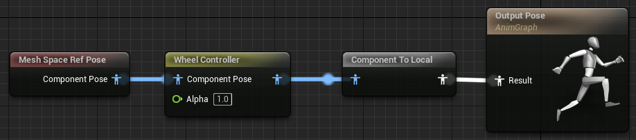
Right-click in the Anim Graph and search for then select Mesh Space Ref Pose.
-
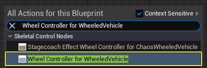
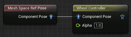
Right-click in the Anim Graph and search for then select Wheel Controller for WheeledVehicle. Connect the Mesh Space Ref Pose node to the Wheel Controller node.
-
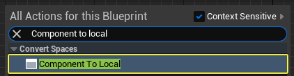
Right-click in the Anim Graph and search for then select Component To Local. Connect the Wheel Controller node to the Component To Local node. Connect the Component To Local node to the Output Pose node.
-
(Optional Step) If you have additional struts or other suspension needs (like the sample Buggy from Vehicle Game), you will need additional nodes in the Animation Graph to handle the joints that affect those polygons. For example, in the Buggy, the extra joints are used to control the axle connections to the wheels. These are driven by Look At nodes, which, when given the wheel joints, will be driven by the Wheel Controller node. The Look At nodes will ensure the suspension stays attached to the wheels, as demonstrated in the following example.
The Buggy uses the following Look At node composition:
| Bone | Look At |
|---|---|
| F_L_Suspension | F_L_wheelJNT |
| F_R_Suspension | F_R_wheelJNT |
| B_L_Suspension | B_L_wheelJNT |
| B_R_Suspension | B_R_wheelJNT |
| B_L_wheelJNT | B_L_Suspension |
| B_R_wheelJNT | B_R_Suspension |
Creating a Vehicle Blueprint
In this section, you will create the Vehicle Blueprint that uses all the assets created in the previous sections.
-
In the Content Browser, right-click and select Blueprint Class from the Create Basic Asset category.

-
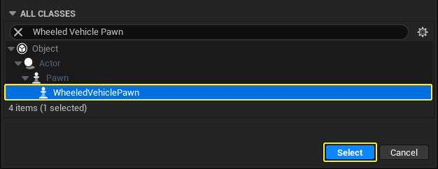
In the Pick Parent Class window, expand the All Classes section and search for and select WheeledVehiclePawn. Click Select to create the new Blueprint asset.
-
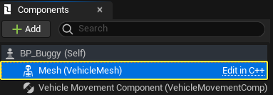
In the Content Browser, double-click the Vehicle Blueprint to open it.
-
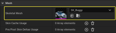
In the Components window, click the Mesh Skeletal Mesh Component. Go to the Details panel and under the Mesh section click the Skeletal Mesh dropdown. Select your vehicle's Skeletal Mesh asset.
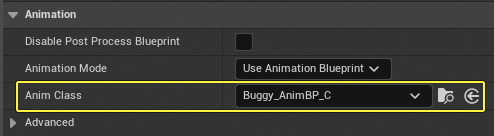
-
In the Details panel, scroll to the Animation section and click the Anim Class dropdown. Select your vehicle's Animation Blueprint.
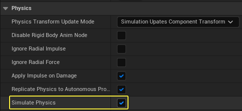
-
In the Details panel, scroll to the Physics section and enable the Simulate Physics checkbox.
-
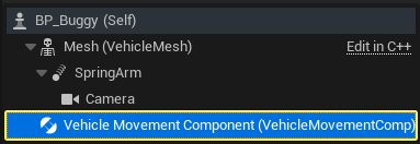
From the Components window, click Add Component, and search for then select Spring Arm.
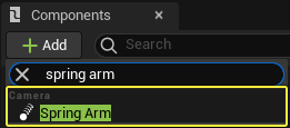
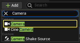
-
With the Spring Arm component selected, click Add Component, and search for then select Camera.
-
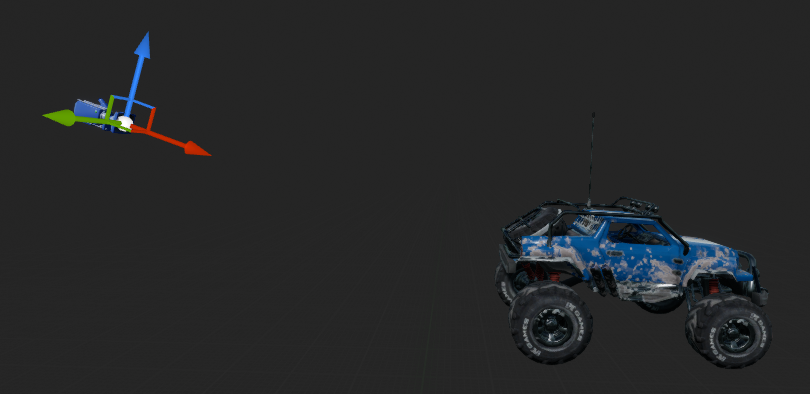
In the Viewport select the Camera and position it to your liking.
-
Select the Camera component and go to the Details panel. Scroll to the Camera Settings section and verify that Use Pawn Control Rotation is disabled.
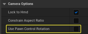
This ensures that the camera is locked to its view direction rather than the Player Controller's view direction.
-
Select the Vehicle Movement Component in the Components window.
-
Go to the Details panel and scroll to the Vehicle Setup section. Expand the arrow next to Wheel Setups and set the following for each wheel:
- Set the Wheel Class to the Wheel Blueprint(s) you created.
- Set the Bone Name to the name of the joint that should be controlled by the wheel.
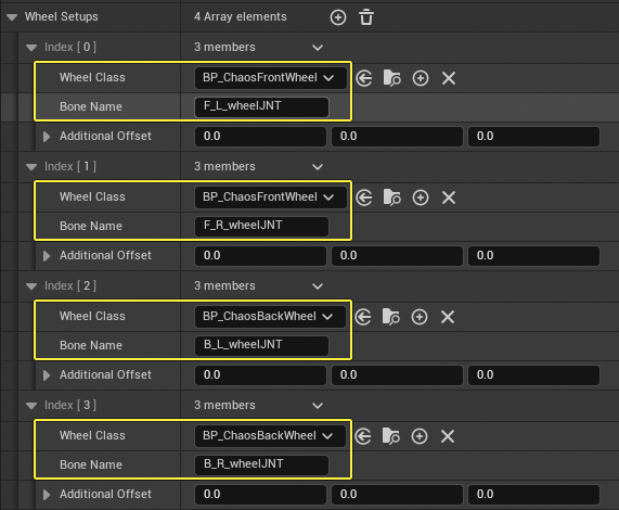
The order you assign the wheels has no bearing on whether it is a front or a rear wheel, only the Bone Name and Wheel Class have any effect. For organizational purposes, we recommend keeping the wheels in the same order for each new vehicle (for example: FL, FR, BL, BR). Keeping a standard helps when you access wheel data by wheel index (the index in the Wheel Setup array).
If the vehicle requires more than 4 wheels, click the + icon next to the Wheel Setups property to add more, or conversely remove wheels as needed.
-
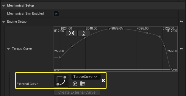
Select the Vehicle Movement Component in the Components window and go to the Details panel. Scroll down to the Mechanical Setup section and expand the Engine Setup category. Expand the Torque Curve category and add the torque curve asset to the External Curve dropdown.
Setting up Vehicle Control Inputs
-
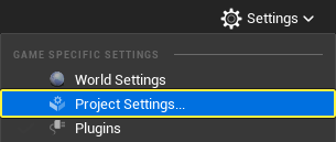
Click Settings > Project Settings to open the Project Settings window.
-
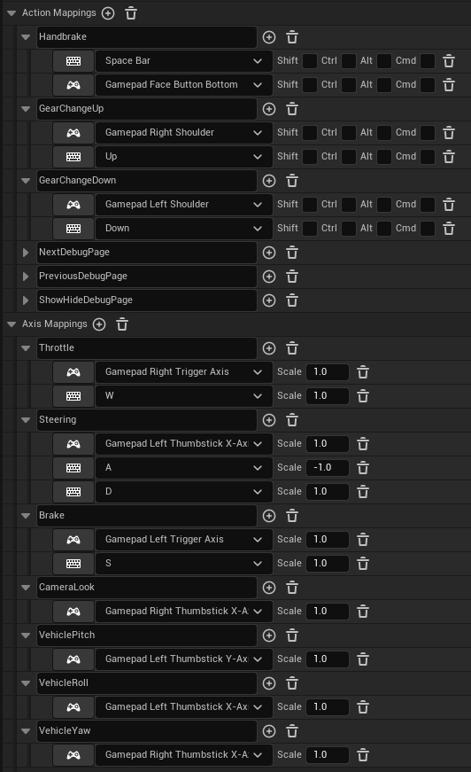
Go to the Input category and set up control inputs for steering, throttle, brake, and handbrake. The image below shows the inputs for the Buggy in the Vehicle Game.
-
In the Content Browser, double-click the Vehicle Blueprint to open it.
-
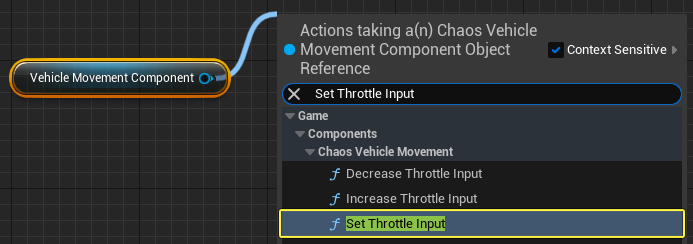
Drag the Vehicle Movement Component to the Event Graph to create a node.
-
Drag from the Vehicle Movement Component node and search for then select Set Throttle Input.
-
-
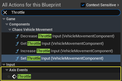
Right-click in the Event Graph and search for then select Throttle to add your Throttle input event.
-
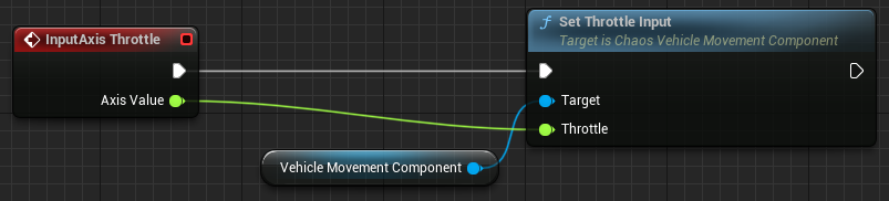
Connect the InputAxis Throttle node to the Set Throttle Input node. Connect the Axis Value pin from the InputAxis Throttle node to the Throttle pin of the Set Throttle Input node.
-
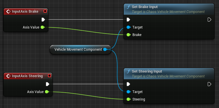
Follow the steps above and add the nodes for Set Brake Input and Set Steering Input, and connect them with their corresponding input events.
-
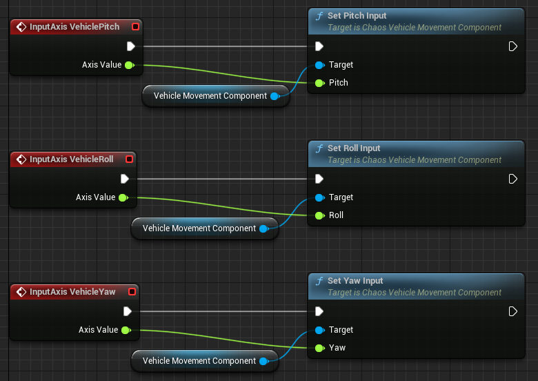
Follow the steps above and add the nodes for Set Pitch Input, Set Roll Input and Set Yaw Input, and connect them with their corresponding input events.
-
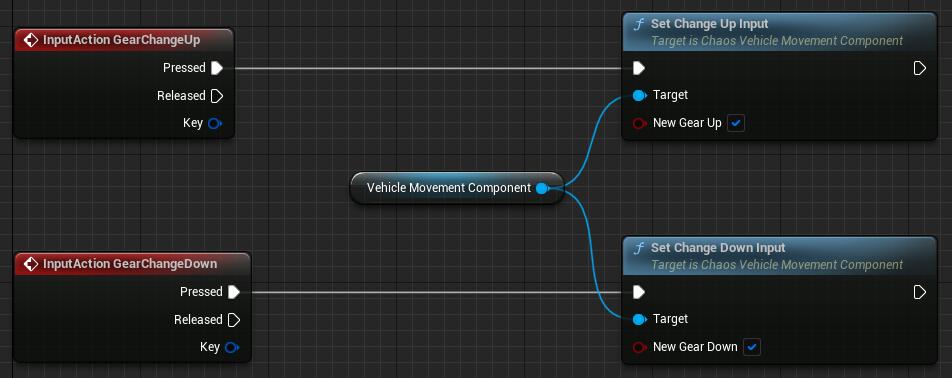
Follow the steps above and add the nodes for Set Change Up Input and Set Change Down Input, and connect them with their corresponding input events.
-
Enable the New Gear Up checkbox on the Set Change Up Input node.
-
Enable the New Gear Down checkbox on the Set Change Down Input node.
-
-
Follow the steps above and add the node for Set Handbrake Input twice, and connect each node to the Pressed and Released pins of the InputAction Handbrake node. Enable the New Handbrake checkbox on the Set Handbrake Input node connected to the Pressed pin.

Vehicle Game Mode Setup
-
In the Content Browser, right-click and select Blueprint Class from the Create Basic Asset category.
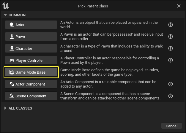
-
In the Pick Parent Class window, select Game Mode Base to create the Game Mode Blueprint.
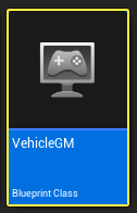
-
In the Content Browser, double-click the new Game Mode Blueprint to open it.
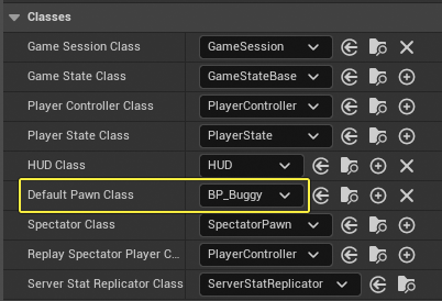
-
Go to the Details panel and scroll to the Classes section. Click the Default Pawn Class dropdown and select your Vehicle Blueprint.
-
Click Compile and Save, then close the window.
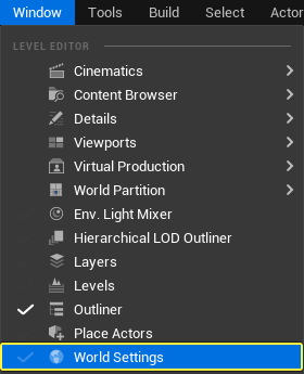
-
In the Main Viewport window, click Window > World Settings to open the World Settings panel.
-
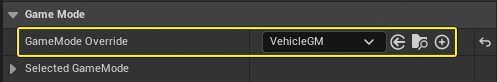
Go to the World Settings panel and scroll down to the Game Mode section.
-
Click the GameMode Override dropdown and select your Game Mode Blueprint.
-
-
Press Play and test your vehicle.
If you have an existing PhysX vehicle that you want to convert to Chaos, follow the PhysX to Chaos Vehicle Conversion guide.