
This quick start guide will teach you how to fracture a static mesh and destroy it by using Unreal’s Dataflow graph system, instead of the traditional workflow which uses the Fracture mode in the editor.
Before reading this guide, please read the Destruction Quick Start guide to learn how to destroy a static mesh using the traditional workflow. This guide will follow the same steps, but use Dataflow instead of the Fracture mode.
1 - Required Setup
-
Create a new project and select the Games category and the First Person template. Enter your project's name and click Create.
Click for full view.
-
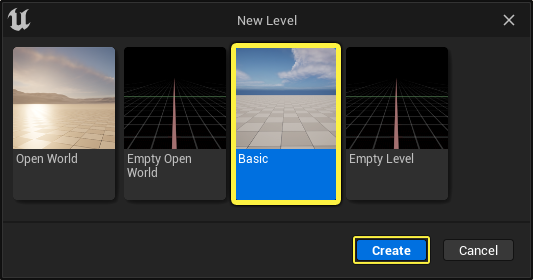
In the editor, click File > New Level. Select the Basic template and click Create. Save the level.
Section Results
In this section, you created a new project and set it up so you can add a static mesh which can be fractured in the next section of this guide.
2 - Creating the Geometry Collection
In this section you will create a Geometry Collection from a static mesh actor.
-
Add a static mesh to the level which you'll use to create a fractured mesh. In this example, I'm using the Chaos Primitive Box included in the Content Examples project available on Fab.
Click for full view.
-
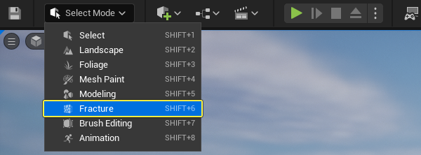
Click the Mode dropdown and select Fracture.
-
Go to the Generate section and click New to create a new Geometry Collection.
Click for full view.
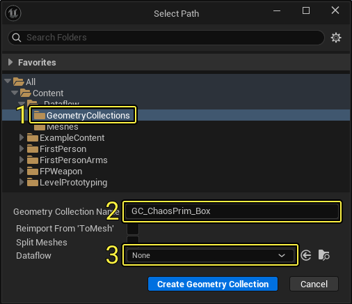
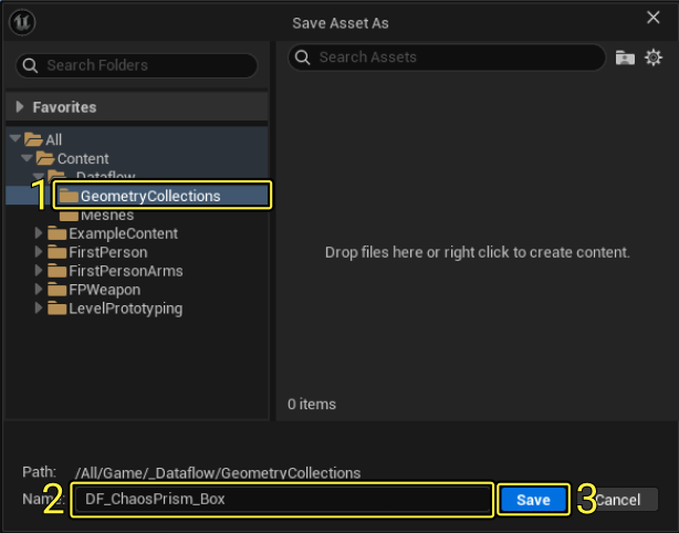
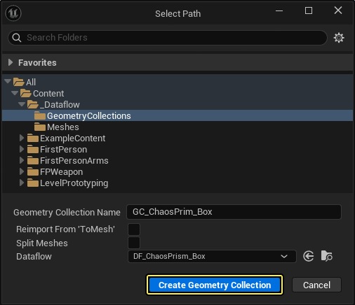
- The Select Path window will open.
- (1) Select the directory location where the Geometry Collection will be saved.
- (2) Enter the name of the asset.
- (3) Click the Dataflow dropdown.
-
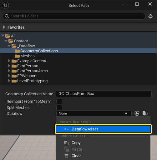
Click DataFlowAsset under the Create New Asset category.
- (1) Select the directory location where the asset will be saved.
- (2) Enter the asset name.
- (3) Click Save.
-
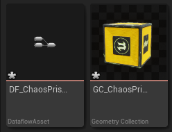
Click Create Geometry Collection to create the Geometry Collection and a Dataflow asset.
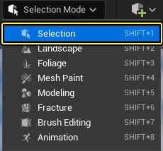
- Click Selection Mode > Selection to go back to the Selection mode in the editor.
- Double click the Geometry Collection asset in the Content Browser to open it.
- In the Geometry Collection window you will see a Dataflow Graph panel where you can enter the Dataflow nodes to fracture the Geometry Collection.
Click for full view.
Section Results
In this section you learned how to create a Geometry Collection with a Dataflow asset associated with the collection.
In the next section you will learn how to fracture the Geometry Collection by creating a Dataflow node graph.
3 - Fracturing the Geometry Collection
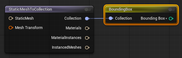
- Right click on the Dataflow graph and search for then select Static Mesh To Collection.
- With the node selected, go to the Asset Details panel and scroll down to the Asset section.
- Click the Static Mesh dropdown and select the static mesh to convert to a Geometry Collection.

-
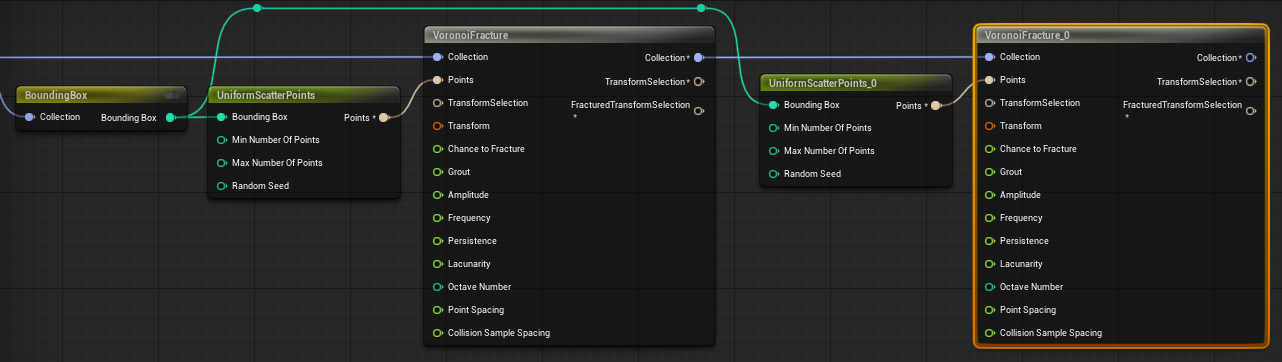
Drag from the Collection pin of the Static Mesh to Collection node and search for then select Bounding Box.
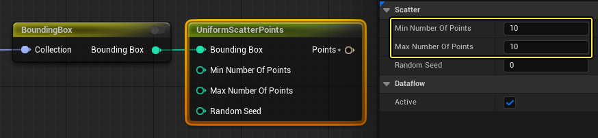
- Drag from the Bounding Box pin of the Bounding Box node and search for then select Uniform Scatter Points.
- Go to the Scatter section and enter 10 for the Min and Max Number of Points.
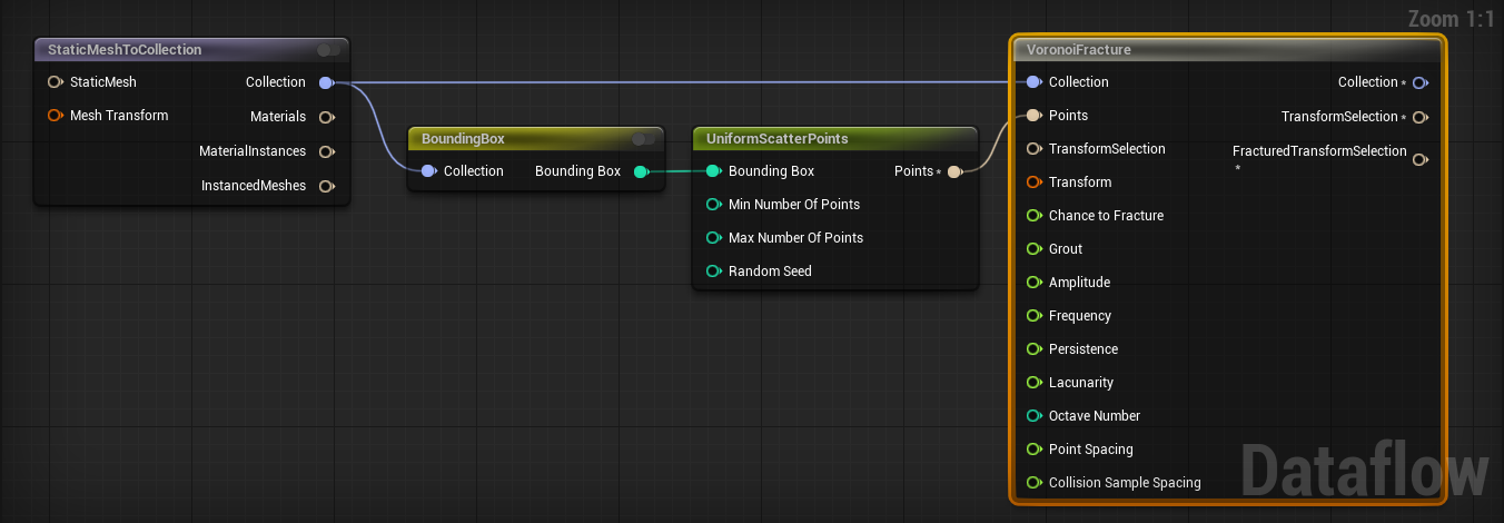
- Drag from the Collection pin of the Static Mesh to Collection node and search for then select Voronoi Fracture.
- Connect the Points pin from the Uniform Scatter Points node to the Points pin of the Voronoi Fracture node.
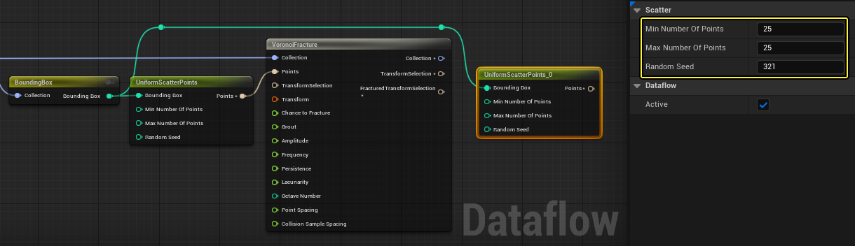
- Drag from the Bounding Box pin of the Bounding Box node and search for then select Uniform Scatter Points.
- Go to the Scatter section and enter 25 for the Min and Max Number of Points.
- Enter a Random Seed number.
- Drag from the Collection pin of the Voronoi Fracture node and search for then select Voronoi Fracture.
- Connect the Points pin of the Uniform Scatter Point node to the Points pin of the Voronoi Fracture node.
-
Drag from the Collection pin of the Voronoi Fracture node and search for then select Auto Cluster. Connect the Transform Selection pin of the Voronoi Fracture node to the Transform Selection pin of the Auto Cluster node.
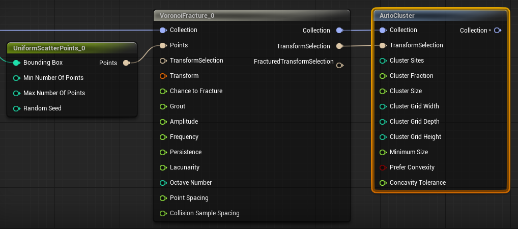
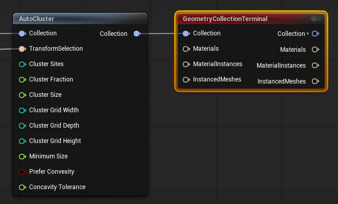
- Drag from the Collection pin of the Auto Cluster node and search for then select Geometry Collection Terminal.
- Connect the Material Instances and Instanced Meshes pins from the Static Mesh to Collection node to the Material Instances and Instanced Meshes pins of the Geometry Collection Terminal node.
Click for full view.
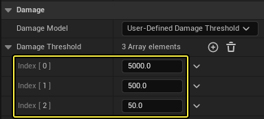
- Go to the Damage section and expand the Damage Threshold array.
- Enter 5000, 500, and 50 for the damage amounts.
- Drag the Geometry Collection from the Content Browser into the level and move it above the ground.
- Click the Play Mode options button and select Simulate or Selected Viewport to see the results.

-
Below you can see the Geometry Collection fracturing when it hits the ground.
Section Results
In this section you learned how to fracture the Geometry Collection by creating a Dataflow node graph.
In the next section you will learn how to destroy the Geometry Collection by shooting it.
4 - Destroying the Geometry Collection by shooting it
In this section you will use the First Person Rifle Blueprint that comes with the template to shoot and destroy the Geometry Collection you created.
You will modify the projectile Blueprint to apply an external strain to the Geometry Collection and trigger the fracture.
-
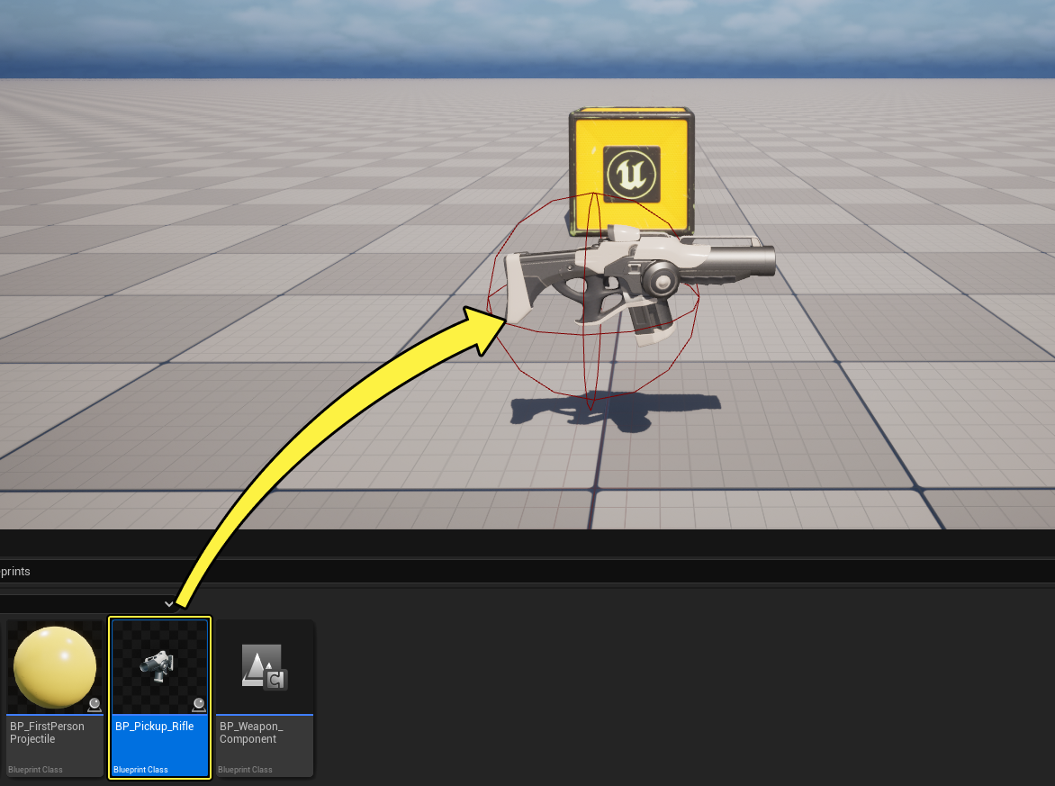
In the Content Browser go to FirstPerson > Blueprints and drag BP_Pickup_Rifle to the level. During gameplay you can pick up the rifle and shoot by using the left mouse button.
-
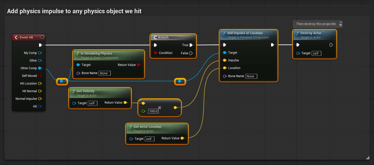
In the same folder, double-click BP_FirstPersonProjectile to open it. In the Event Graph, select all the nodes except Event Hit and delete them.
-
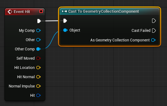
Drag from the Other Comp pin of the Event Hit node and search for then select Cast to Geometry Collection Component.
-
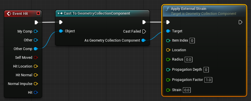
Drag from the As Geometry Collection Component pin of the Geometry Collection Component node and search for then select Apply External Strain.
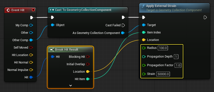
- Drag from the Hit pin of the Event Hit node and search for then select Break Hit.
- Connect the Location and Hit Item pins of the Break Hit Result node to the Location and Item Index pins of the Apply External Strain node.
- Set the Radius to 100, the Propagation Depth and Propagation Factor to 1, and Strain to 50000.
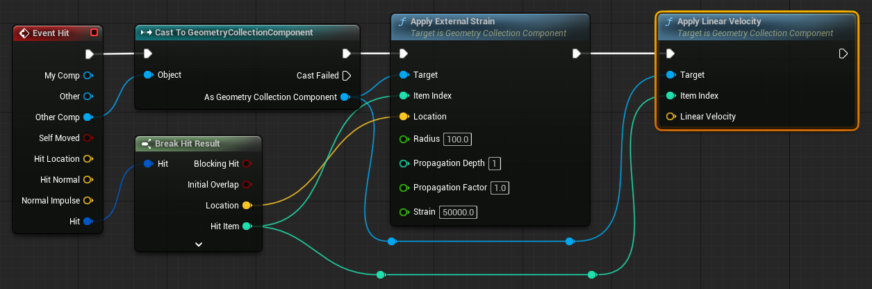
- Drag from the Apply External Strain node and search for then select Apply Linear Velocity.
- Connect the Hit Item pin of the Break Hit Result node to the Item Index pin of the Apply Linear Velocity node.
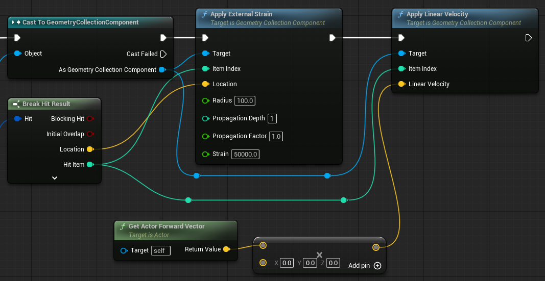
- Right click in the Event Graph and search for then select Get Actor Forward Vector.
- Drag from the Return Value pin of the Get Actor Forward Vector node and search for then select multiply.
- Connect the Multiply node to the Linear Velocity pin of the Apply Linear Velocity node.
-
Create a Float variable and name it Linear Velocity. Set its default value to 500.
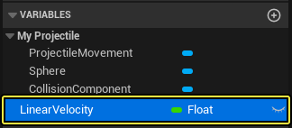
- Connect the Linear Velocity variable to the Multiply node.
- Compile and Save.
Click for full view.
-
Press Play and move to the rifle to pick it up. Use the left mouse button to shoot a projectile at the Geometry Collection and destroy it
Section Results
In this section you learned how to apply an external strain to the Geometry Collection when the projectile hits it.
5 - Modifying the Dataflow Graph
Fracturing a Different Static Mesh
You can quickly change the static mesh used by the Dataflow graph to see how other meshes look when fractured the same way.
Select the Static Mesh to Collection node and change the Static Mesh in the Asset section.
Changing the Point Pattern
You can change the scatter point pattern used by the fracture node by replacing the Uniform Scatter Points node with another pattern.
Changing the Fracture Pattern
You can also experiment with different fracture patterns by replacing the fracture node used in the Dataflow graph.
Section Results
In this section you learned how you can quickly modify the fractured Geometry Collection by changing the static mesh, point patterns, or fracture patterns in the Dataflow graph.
5 - On Your Own!
Now that you know how to generate and destroy Geometry Collections using Dataflow, try experimenting with different nodes and parameters to see how your results change.