
%Description%
Constant
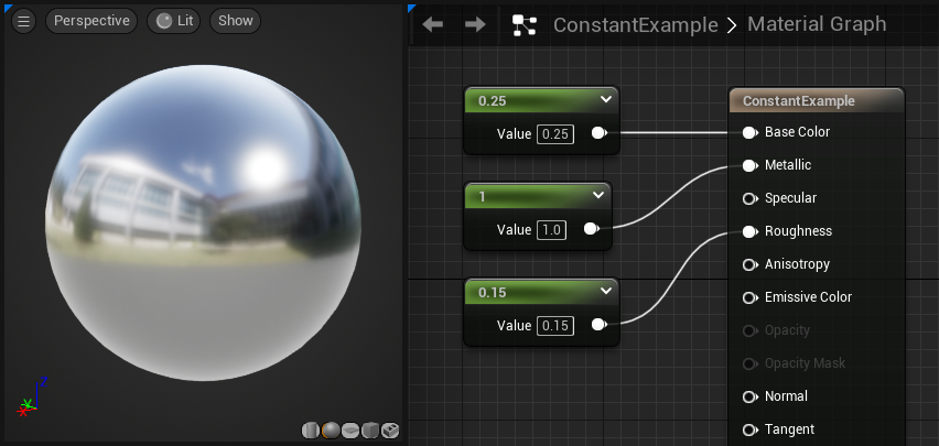
The Constant Material Expression outputs a single float value. It is one of the most commonly used expressions and is compatible with any input, regardless of the number of channels the input expects.
For instance, if you connect a Constant to an input expecting a 3-channel vector, the constant value is used for all 3 elements. When supplying a single number, it can be useful to collapse the node using the small triangle icon in the description area.
| Property | Description |
|---|---|
| R | Specifies the float value the expression outputs. |
Examples: 0.7, -0.24, 1.1
You can quickly create a Constant expression by holding the 1 key and left-clicking in the background of the Material Graph in the Material Editor.
Constant2Vector
The Constant2Vector expression outputs a two-channel vector value, in other words, two constant numbers.
| Property | Description |
|---|---|
| R | Specifies the float value of the red (first) channel of the vector the expression outputs. |
| G | Specifies the float value of the green (second) channel of the vector the expression outputs. |
Examples: (0.4, 0.6), (1.05, -0.3)
Example Usage: The Constant2Vector is useful for modifying texture scale or offset, as UV coordinates require two-channel values.

To quickly create a Constant2Vector node, hold the 2 key and left-click anywhere in the background of the Material Graph.
Constant3Vector
The Constant3Vector expression outputs a three-channel vector value, in other words, three constants numbers. A Constant3Vector is often used to define a solid RGB color, where each channel is assigned to a color (red, green, blue). You can double-click the Constant3Vector node in the Material Graph to summon a color picker dialog.
| Property | Description |
|---|---|
| R | Specifies the float value of the red (first) channel of the vector the expression outputs. |
| G | Specifies the float value of the green (second) channel of the vector the expression outputs. |
| B | Specifies the float value of the blue (third) channel of the vector the expression outputs. |
Examples: (0.4, 0.6, 0.0), (1.05, -0.3, 0.3)
In this example an Constant3Vector is multiplied by a Texture Sample to change the tint of the texture.

To quickly create a Constant3Vector node, hold 3 key and left-click anywhere in the Material Graph.
Constant4Vector
The Constant4Vector expression outputs a four-channel vector value, in other words, four constant numbers. You can use the Constant4Vector expression to define RGBA color, where each chanel is assigned to a color (red, green, blue, alpha).
| Property | Description |
|---|---|
| R | Specifies the float value of the red (first) channel of the vector the expression outputs. |
| G | Specifies the float value of the green (second) channel of the vector the expression outputs. |
| B | Specifies the float value of the blue (third) channel of the vector the expression outputs. |
| A | Specifies the float value of the alpha (fourth) channel of the vector the expression outputs. |
Examples: (0.4, 0.6, 0.0, 1.0), (1.05, -0.3, 0.3, 0.5)
In the example below, a Constant4Vector expression is used to define both the Base Color and Opacity of the Material. The top pin outputs the RGB color, while the bottom pin outputs the value in the alpha channel. The alpha value of 0.5 results in a semi-transparent Material.

To quickly create a Constant4Vector, hold the 4 key and left-click anywhere in the background of the Material Graph.
Distance Cull Fade
The DistanceCullFade expression outputs a scalar value that fades from black to white and can be used to smoothly fade an object in once it passes within the cull distance. This node is primarily used to prevent Static Meshes from abruptly "popping" in and out of visibility when they fall outside the cull distance.
In this example, a sphere is placed within a CullDistanceVolume with a cull distance of 3000 units. The Material shown on the right is applied to the sphere.
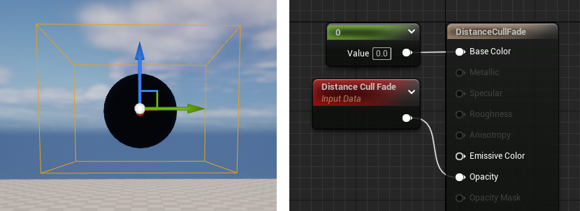
When playing the level in the Editor, the sphere smoothly fades in and out as the camera moves in and out of the cull distance.
ParticleColor
The ParticleColor expression ties into the current color of a given particle based on any per-particle color data defined within Cascade. This must be plugged into the appropriate channel (Emissive Color).
| Item | Description |
|---|---|
| Outputs | |
| RGB | Outputs the combined RGB vector data. |
| R | Outputs the red channel data. |
| G | Outputs the green channel data. |
| B | Outputs the blue channel data. |
| A | Outputs the alpha channel data. |
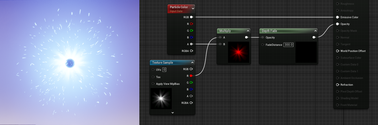
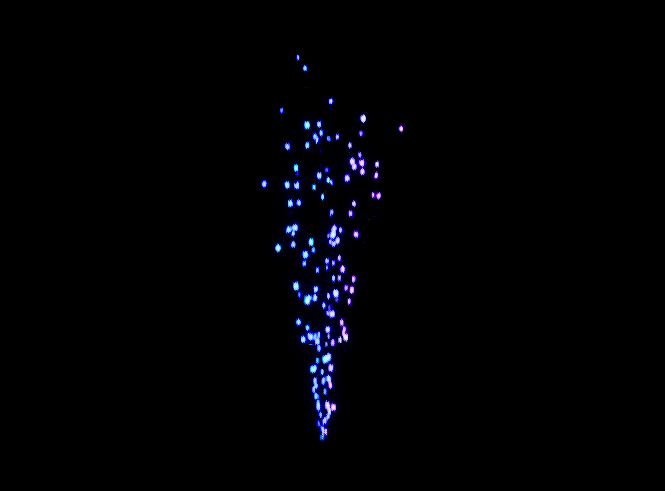
In this example, you can see where the ParticleColor expression is providing color to the particles as defined within the particle system.
ParticleDirection
The ParticleDirection expression outputs Vector3 (RGB) data on a per-particle basis, representing the direction a given particle is currently traveling.
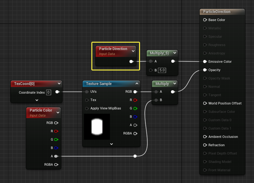
You can see in the comparison below how the color of the particles is changing based on the current direction each particle is traveling.
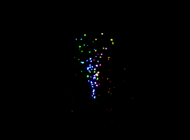
Note how the color changes as the particles change directions.
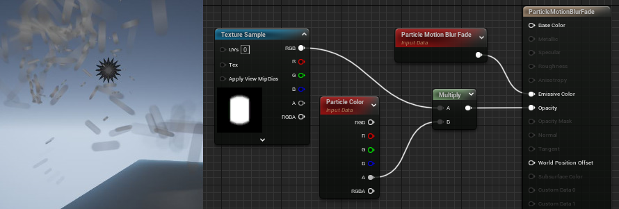
ParticleMotionBlurFade
The ParticleMotionBlurFade expression outputs a value representing the amount of fade on a particle as a result of motion blur. A value of 1 represents no blur, black represents complete blur.
ParticleRadius
The ParticleRadius expression outputs the radius in Unreal units of each particle individually. This allows, for example, for changes to be made to a material once the radius has reached a certain point.

In this image, the particles are shifting from green to red as their radius exceeds 7 units.
ParticleRelativeTime
The ParticleRelativeTime expression outputs a number between 0 and 1 representing a particle's age, with 0 being the moment of birth and 1 being the moment of death.
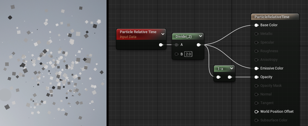
In this example, you can see the particle relative time fed into the emissive color, resulting in particles that are fading from black at the moment of birth to white as they approach death.
ParticleSize
The Particle Size expression outputs the X and Y size of a particle sprite. This can then be used to drive some aspect of a Material.

Click image for full view.
In the example above, Particle Size is being multiplied into Particle Color. Notice that we are masking the output so that we only use the Green channel, which corresponds to the Y-Axis, or the length of the particles. This means that as the particles stretch out, they become brighter in color. As they shrink, they will become dimmer.
ParticleSpeed
ParticleSpeed outputs the current speed each particle is traveling, measured in Unreal units per second.
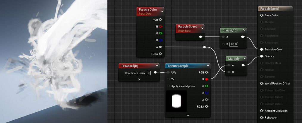
In this example, particle speed is feeding the color of the particles, which is then divided by 10 provide more meaningful results. The particles become black as they slow down.
PerInstanceFadeAmount
The PerInstanceFadeAmount expression outputs a float value from 0 to 1 based on the cull distance applied to an instanced Static Mesh, such as foliage. It is constant, but can be a different number for each individual instance of a mesh. The node is often used to fade foliage in and out gradually, rather than having it abruptly pop in or out of the scene when the cull distance on the InstancedFoliageActor is reached.
This rock Material uses the Translucent Blend Mode, with a PerInstanceFadeAmount expression plugged into the Opacity input. The Cull Distances on the InstancedFoliageActor are set to 1000 and 2500.
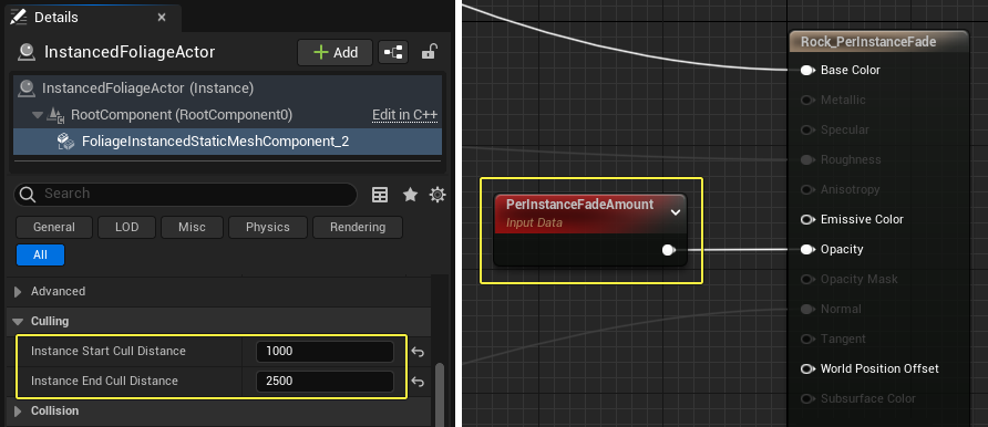
Note how the rock instances fade out with distance when the camera flies over the scene. This improves performance in levels with heavy amounts of foliage.
This only works when applied to an InstancedStaticMesh Actor or other Actor which utilizes InstancedStaticMeshComponents.
PerInstanceRandom
The PerInstanceRandom expression outputs a different random float value per Static Mesh instance to which the Material is applied. InstancedStaticMeshComponent sets a random float for instance, which is exposed so that it can be used for whatever is desired (random light levels behind a window, for example). It is constant, but different, for each instance of the mesh.
The output value is a whole number between 0 and RAND_MAX for the target platform. This Material uses the PerInstanceRandom expression to provide a random emissive value per instance.
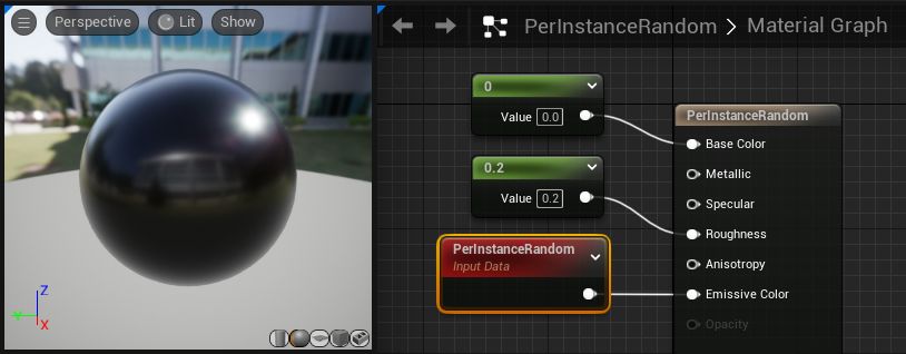
When the Material is applied to a sphere and instanced with the foliage system, each instance of the sphere has a different emissive value.
This only works when applied to an InstancedStaticMesh Actor or other Actor which utilizes InstancedStaticMeshComponents.
Time
The Time node is used to add the passage of time to a Material. It is used with Material Expressions that change over time, such as a Panner, Cosine, or other time-dependent operations.
| Property | Description |
|---|---|
| Ignore Pause | If true, time will continue to march on even if the game is paused. |
| Period | If true, this will be the amount at which to wrap around time. On Mobile Materials, this will perform the Period computation on the CPU at full-precision, whereas on the GPU it will run at half precision (potentially having issues on periods longer than a minute). |
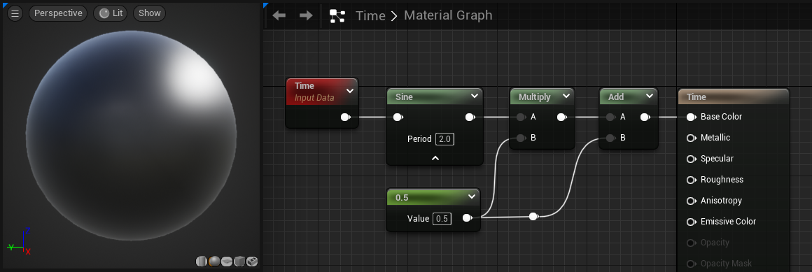
The Material network shown in the image above creates a Material that changes over time, constantly exhibiting a sinusoidal transition between white and black. When period is enabled, setting period to 0 effectively stops the transition. A value of 1 is the same as if the period property is false. Setting the number closer to 0 makes the Material change at a more rapid pace. The results of the graph are shown in the video below.
TwoSidedSign
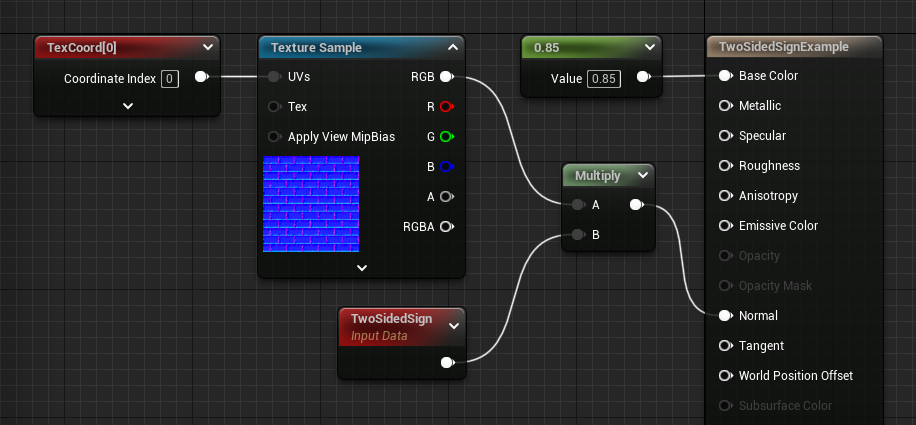
The TwoSidedSign expression is useful for flipping the normal on the backfaces of two sided custom lighting Materials to match the functionality of Phong Shading: +1 for frontfaces, -1 for backfaces of a Two Sided Material.
In this graph, the normal map is multiplied by a TwoSidedSign expression.
The comparison image below shows both sides of the Material with and without the TwoSidedSign expression.
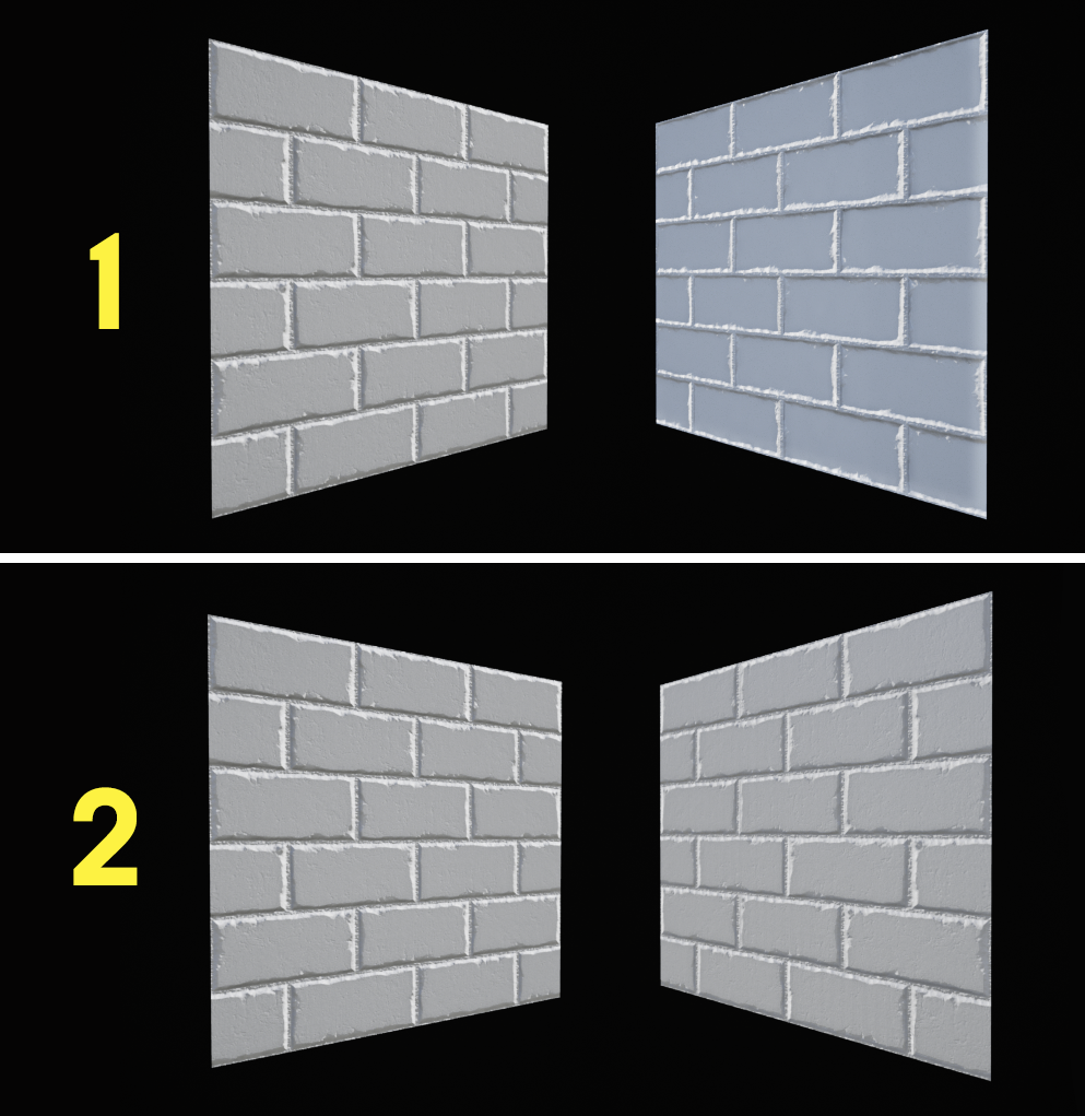
- Top row - Without the TwoSidedSign node, the normals are inverted on the backface and the bricks render incorrectly. The highlights are on the bottom-right corner of each brick instead of the top-left.
- Bottom row - When the Normal map is multiplied by a TwoSidedSign expression (as shown in the graph above), the normals on the backface are correct and the bricks render exactly as they do on the front face.
VertexColor
The VertexColor Material expression enables a Material to utilize Vertex Color data from the Static Mesh on which the Material is applied.
| Outputs | Description |
|---|---|
| RGB | Outputs the combined three-channel RGB vector value of the vertex colors. |
| R | Outputs the red channel of the mesh's vertex colors. |
| G | Outputs the green channel of the mesh's vertex colors. |
| B | Outputs the blue channel of the mesh's vertex colors. |
| A | Outputs the alpha channel of the mesh's vertex colors. |
The VertexColor node is often used as an alpha mask to blend between two or more textures in Mesh Paint Mode.
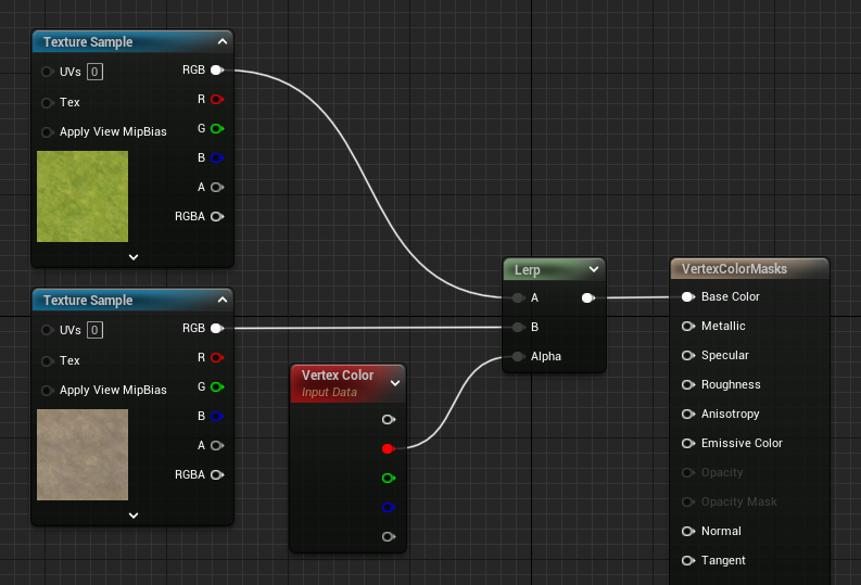
This network uses the red channel of the Vertex Colors to Lerp between the two Texture Samples. When you paint on the red channel in Mesh Paint Mode the gravel texture is revealed.
View Property
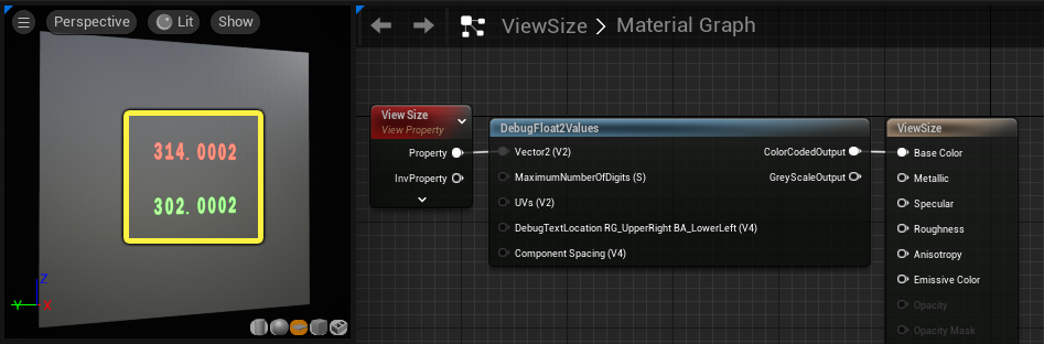
The ViewProperty expression outputs a view dependant constant property such as the field of view or render target size. You can configure which View Property is accessed by selecting the node and using the drop-down menu in the Details Panel.
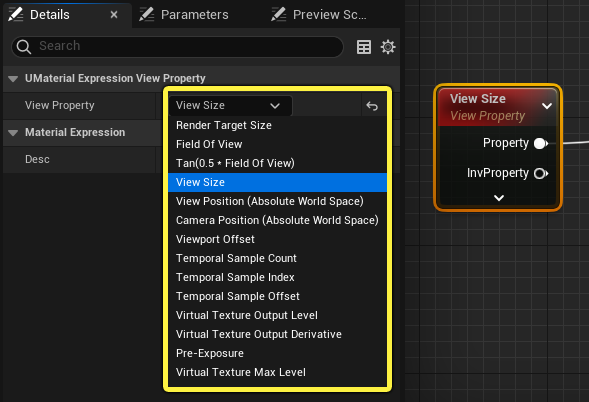
The data type of the output depends on the property selected in the Details Panel. For example, when View Size is selected, the node outputs a two channel vector representing the width and heigh of the viewport in pixels. This is demonstrated below by passing the output through a DebugFloat2Values Material Function. The width and height of the viewport are shown in the preview viewport.
Precomputed AO Mask
The PrecomputedAOMask node provides access to Lightmass-calculated ambient occlusion (AO) in your Material. This is useful for procedural texturing or for adding in aging effects and dirt in areas where it would slowly accumulate over time.
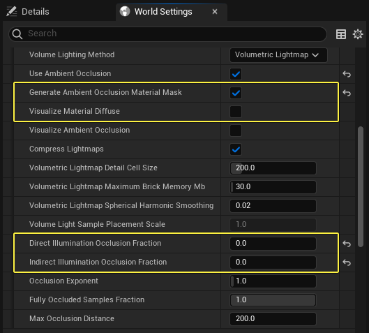
The Precomputed AO Mask only works with baked lighting. Before you can see the results of the Precomputed AO Mask, you need to build the lighting of the level with Lightmass.
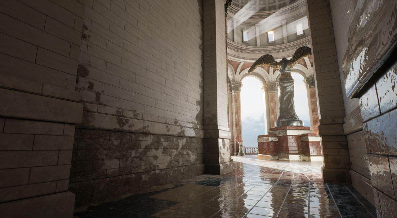
The above screenshot uses an AO mask to blend a dirt layer automatically into corners of the environment. To use AO masks, you'll need to enable both Use Ambient Occlusion and Generate Ambient Occlusion Material Mask under World Settings -> Lightmass settings, and then build lighting. The other AO controls like Max Occlusion Distance can be useful to tweak the look of the AO. Also make sure to set both Direct and Indirect Occlusion Fraction to 0, so that this AO will not be applied to the actual level lighting.
You can access the AO in any Material by using the PrecomputedAOMask Material Expression node. The PrecomputedAOMask works as a 0 to 1 mask with 1 denoting areas that are affected by AO and 0 for areas that are not.
The image below shows how to set up a Material to use the Precomputed AO Mask.
Click image to enlarge.