In this Quick Start guide, you will go through the steps to calibrate lens distortion and the nodal point offset, using the Camera Calibration plugin.
The examples in this guide use a production camera, an optical camera tracking system, and an Blackmagic 8k Pro capture card for source video input.
Prerequisites
You must have the following hardware:
- Camera and lens (Required)
- Knowledge of the lens focal length and focus distances
- Knowledge of the camera's sensor dimensions and resolution including any impact on image size, such as crop factors
- Lens encoding system, Live Link compatible (Best practice)
- In the absence of a lens encoding system, you can manually read and enter the lens parameters into a virtual Live Link subject.
- SDI video feed from the camera via Capture card such as AJA or Blackmagic (Required)
- Camera tracking system, Live Link compatible (Required for nodal offset calibration)
- Camera tracking prop should be positioned above the camera so as to be visible to the camera tracking system (in the case of optical systems) with its root bone and axis set approximately aligned with the camera facing forward.
- Camera tracking is required for nodal offset calibration but not necessary for distortion calibration.
- Printed checkerboards (Required). Recommended to be printed on di-bond or foam board. Several sizes may be required to calibrate for a variety of focus distances or focal lengths. Smaller checkerboards let you calibrate for closer focus distances, and larger checkerboards for further focus distances. Likewise for focal length, larger checkerboards will be more useful for wider angle lenses to improve coverage.
You must set up the following in your Unreal Engine project:
- Camera Calibration plugin
- Camera tracking and focus, iris, zoom (FIZ) data streaming through Live Link
- Specifically, your level must have a CineCamera Actor with the following components added:
- A Live Link Component Controller that has a transform and tracking data from the tracking system. This should be a transform role
- A Live Link Controller component with a source providing lens encoding data. This should be a camera role.
-
A lens component
Some camera tracking systems will have their transform and lens encoding data combined into one camera role, in which case you would just have a single Live Link controller component and a lens component.
- Source video input
- (Required) A Media Source or Media Profile setup to receive your SDI camera feed
- (Optional) Timecode and genlock setup in the Media Profile if you're using a sync generator. To set this up, see Media Profile.
- (Optional) Timed Data Monitor to evaluate sync and timecode.
Create a Lens File Asset
The Lens File asset is the container that stores calibration data about a lens, including lens distortion, nodal offset, and focal length. Double-click the lens file to open the Lens File Asset Editor, which is a useful tool for calculating that data. A new lens file needs to be created for each lens-to-camera body combination.
To create a lens file asset in your project, follow these steps:
-
In the Content Browser, right-click to open the context menu and click Miscellaneous > Lens File.
-
Name the lens file something that describes the camera lens tracker combination, such as "CameraModel_50mm_TrackerA".
-
Assign the lens file to the lens component on the Cinecamera actor.
-
Double-click the lens file asset to open the Lens File Asset Editor. This creates temporary composure camera actors in the level, which are removed when the lens file editor is closed.
-
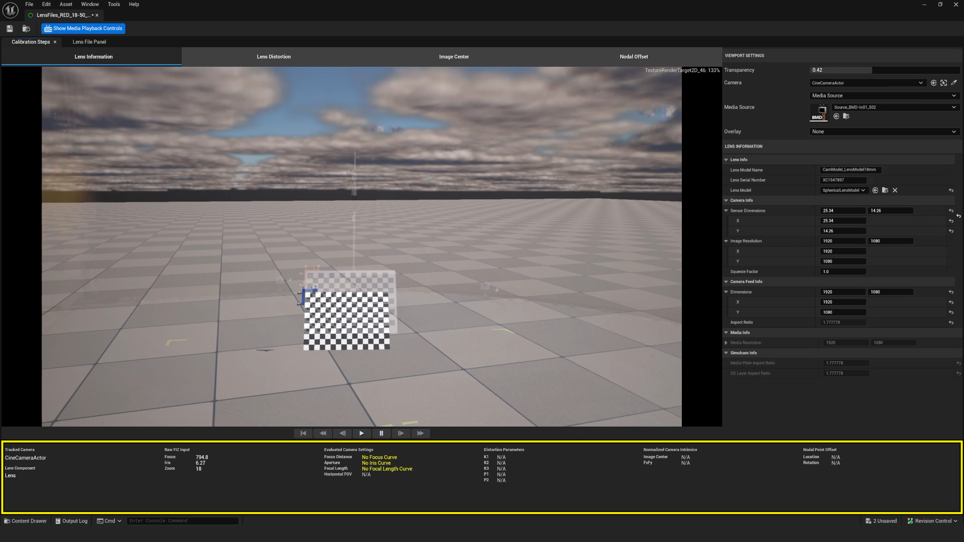
Under Viewport Settings:
-
Set Camera to the Cinecamera actor.
-
Set Media Source to the Media Profile or Media Source and select the correct video device. If video is being received correctly you should now be able to see video composited in the lens file viewport.
-
-
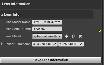
Under Lens Information:
-
Enter a Lens Model Name and Serial Number. A recommended naming convention combines the camera body name and the focal length. These are not required and are useful metadata for the user's benefit.
-
Set the appropriate Lens Model (Spherical or Anamorphic).
-
Set Sensor Dimensions to match your camera's physical sensor size taking into account any crop factors or other camera settings that change the effective sensor size.
-
For anamorphic lenses, set the Squeeze Factor. For spherical lenses, Squeeze Factor should be set to 1.0.
-
Set the image resolution and camera feed info dimensions as appropriate.
The camera feed dimensions are intended to account for aspect ratio differences between the recording resolution and the transmitted media source resolution. If the sensor dimensions were set correctly in the previous step, the camera feed dimensions may have been automatically adjusted by the tool.
-
-
Select your CineCamera actor in the Outliner to open its Details panel.
At the bottom of the Lens File Asset Editor you will find a summary of the current properties applied to the lens file. Most of the properties show as blank or "N/A" at this stage. These properties will update as you continue with the calibration process. After everything is set correctly, you should see a composited image of your Unreal level and the SDI feed, you will also see the name of the cinecamera and lens component, along with corresponding FIZ data in the bottom panel.
Create the Virtual Checkerboard
This step shows how to calculate lens distortion with the common method of using a checkerboard. You can use a printed checkerboard mounted on a rigid surface and held in view of the production camera, or a checkerboard image displayed on a tablet. You will then need to create a Checkerboard actor in UE to match the properties of the physical checkerboard.
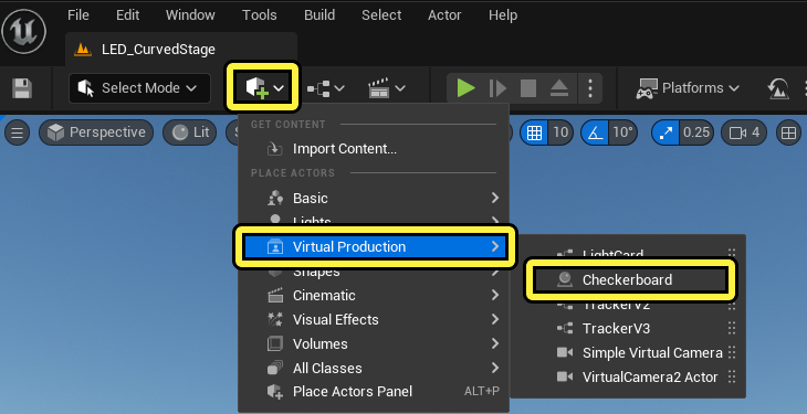
To create a Checkerboard actor, follow these steps:
-
In the Main Toolbar, select Add Content and choose Virtual Production > Checkerboard to add a CameraCalibrationCheckerboard Actor to the level.
-
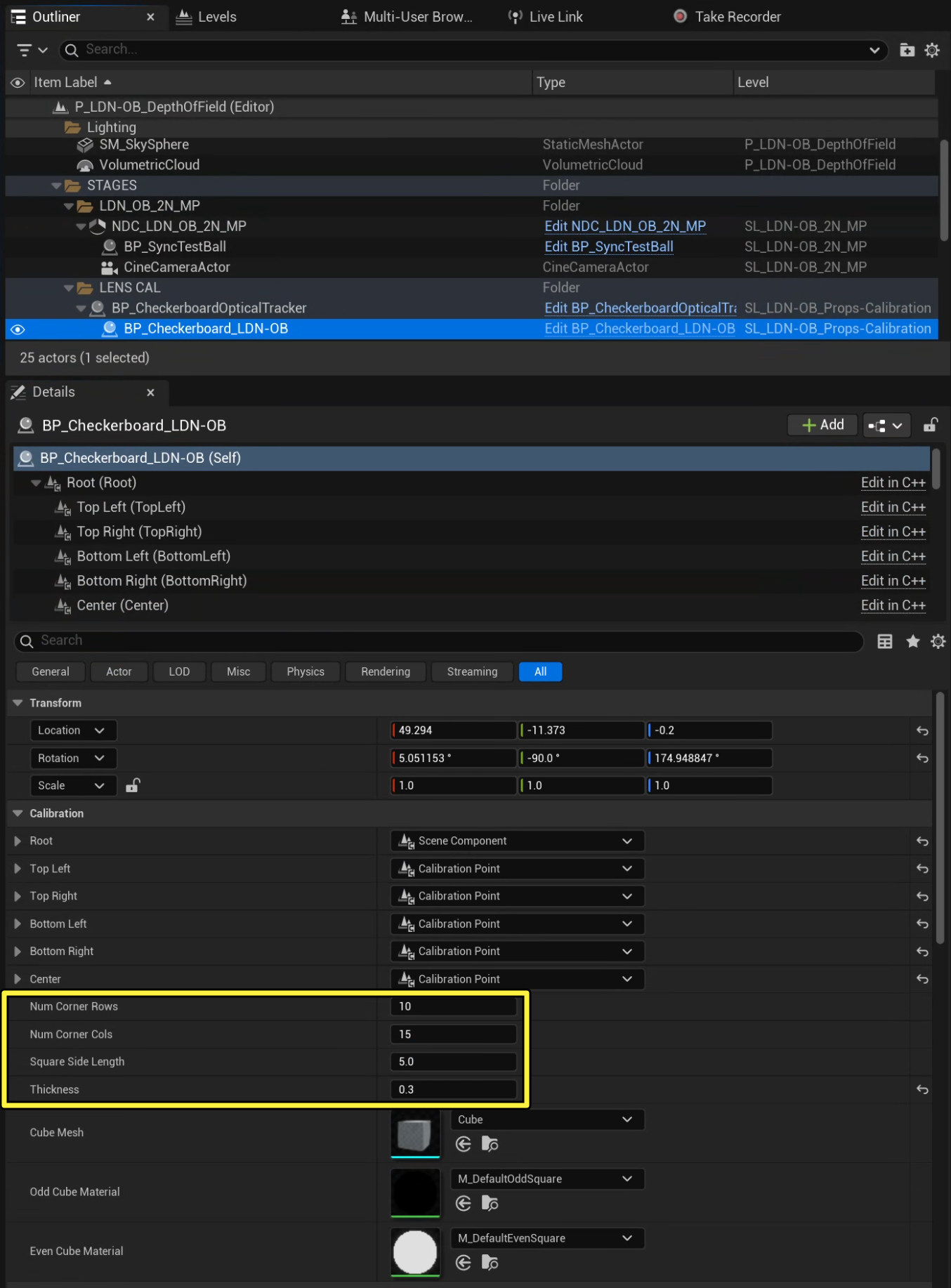
In the Outliner, select the CameraCalibrationCheckerboard actor to open its Details panel. In the Details panel under Calibration:
-
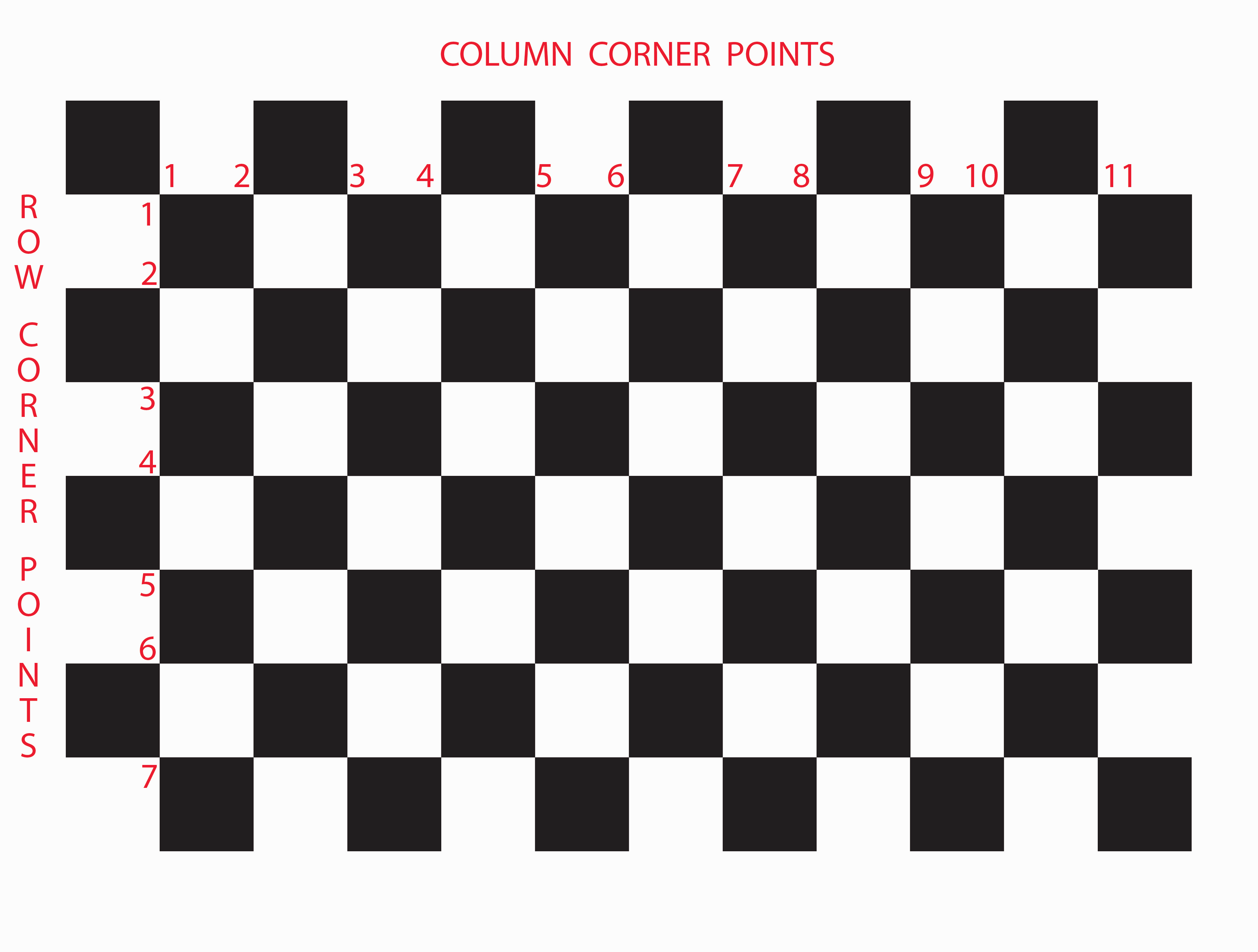
Set Num Corner Rows to the number of corners in one of your checkerboard's columns. In this example, the number of row corners is 7.
-
Set Num Corner Columns to the number of corners in one of your checkerboard's rows. In this example, the number of column corners is 11.
-
Set Square Side Length to the length of a square in your checkerboard in centimeters (cm). In this example, each square side is 4.5 cm.
-
(Optional) Set Thickness to the thickness of the physical checkerboard in cm.
-
Note in the image below that the corner row and columns are counted as the inside of each of the outer black squares:
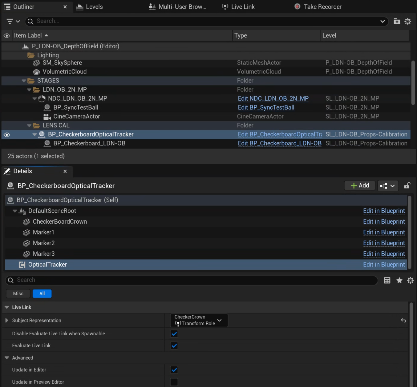
For optimal use of lens calibration, it's important that the alignment of the tracked checkerboard actor is as accurate as possible.
You can calculate the lens distortion and the nodal offset at the same time if you track your checkerboard using Live Link with the same tracking system for the camera. This can be achieved by placing optical markers or a VIVE puck on your checkerboard as appropriate per your tracking system. While the lens calibration aims to compensate for any misalignment between the real world checkerboard and the tracked checkerboard actor, it is recommended that they are at least within 5 centimeters of translation and 5 degrees of rotation on all axes.
To apply the tracking to the checkerboard in Unreal, parent the checkerboard actor to an actor with a Live Link component receiving the Live Link data.
Calibrate Lens Distortion and Nodal Offset
To calibrate the lens distortion and nodal offset simultaneously, follow these steps:
-
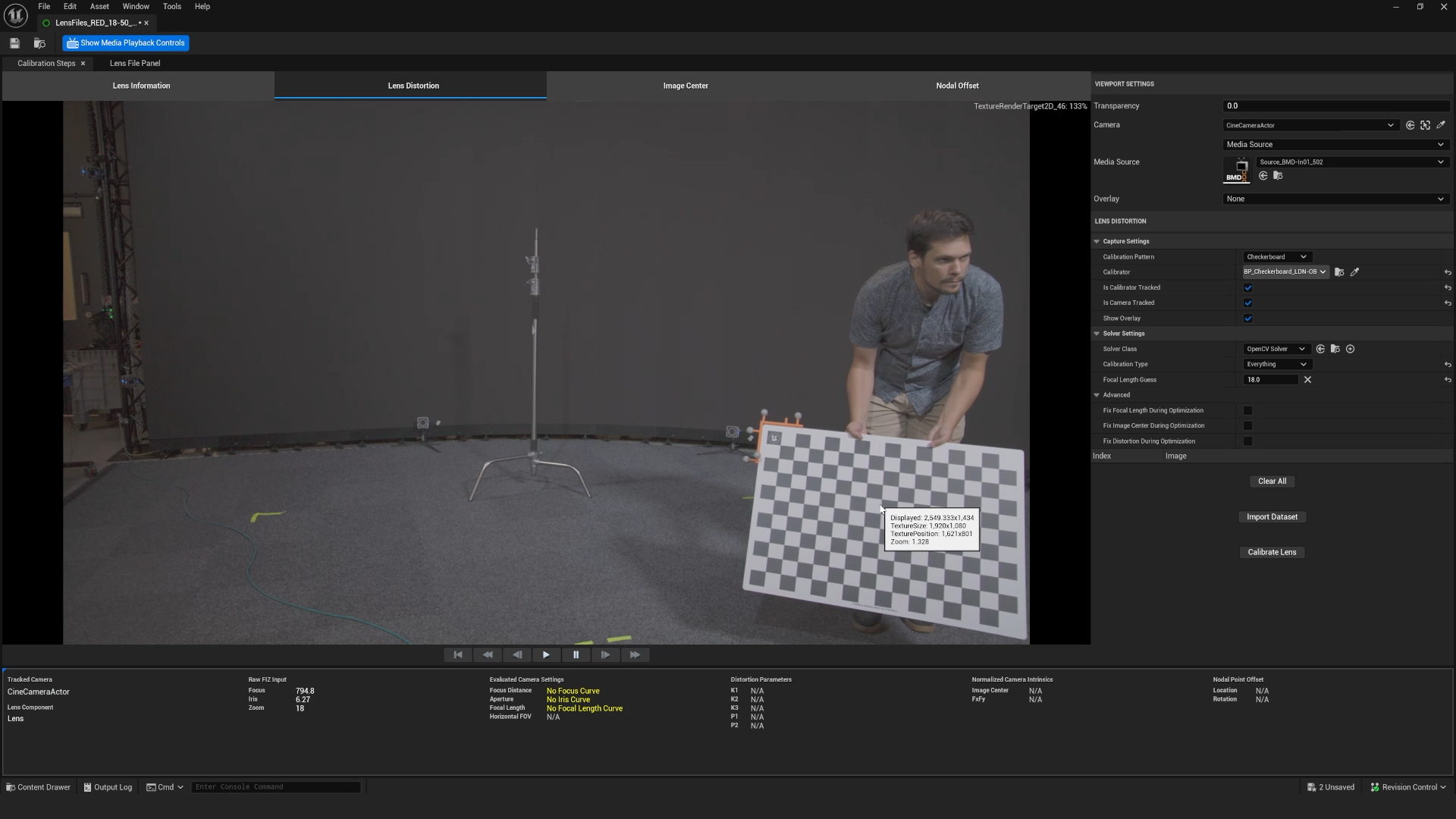
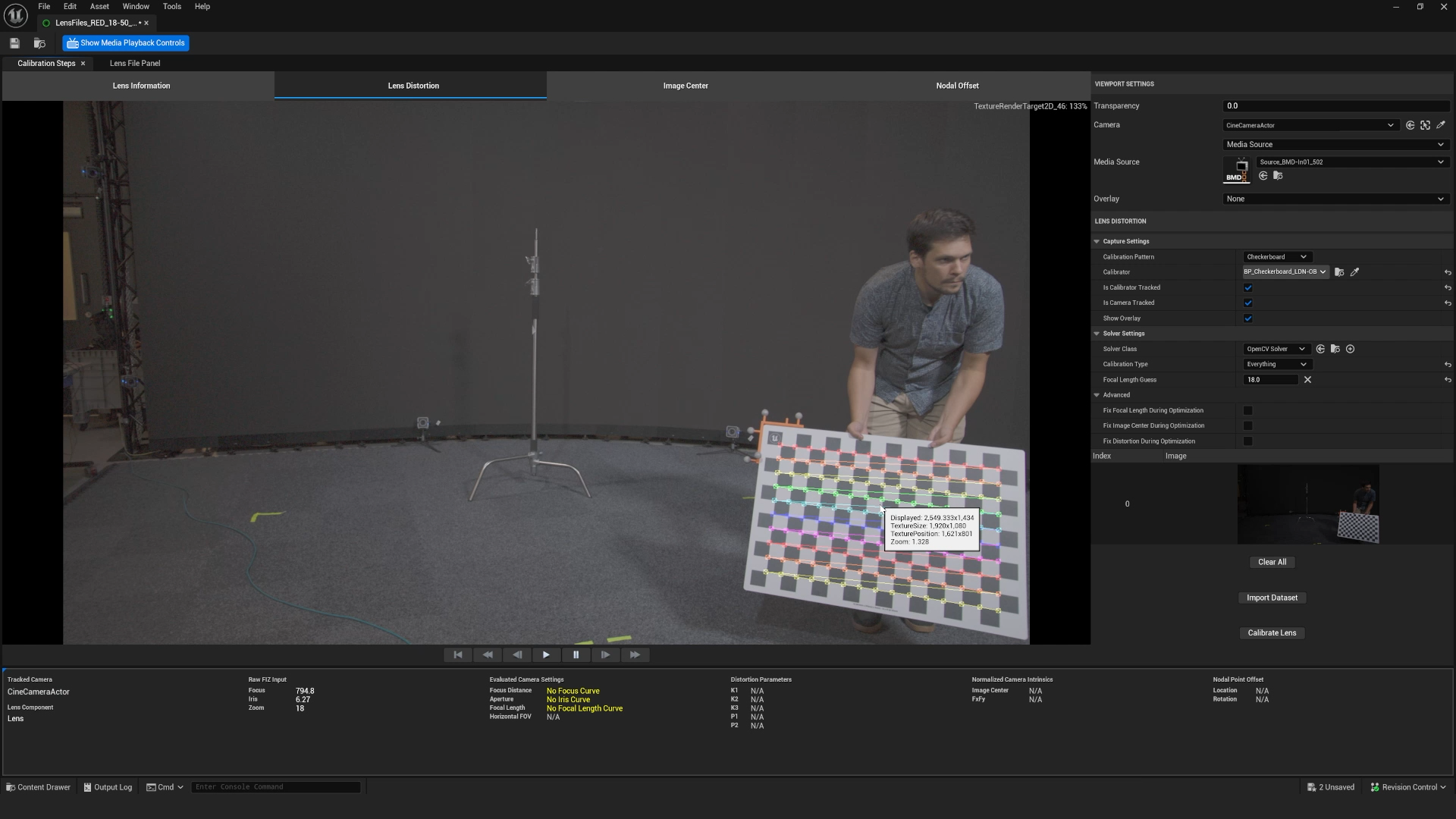
In the Lens File Asset Editor, click the Lens Distortion tab.
-
Click Capture settings, and do the following:
-
Set Calibration Pattern settings to Checkerboard.
-
Set Calibrator to the CameraCalibrationCheckerboard actor you created.
-
Enable Is Calibrator Tracked.
-
Enable Is Camera Tracked.
-
Enable Show Overlay. This will help show an indication of the lens coverage during the data capture phase.
-
-
In Solve Settings, do the following:
- Enable Solve Nodal Offset.
- Click Focal Length Guess > Set to Value and set it to what you expect the focal length to be (for example, 50mm).
-
Place the checkerboard in front of the camera as shown below.
-
Click on the viewport to start the calibration process and create the first image to be used.
-
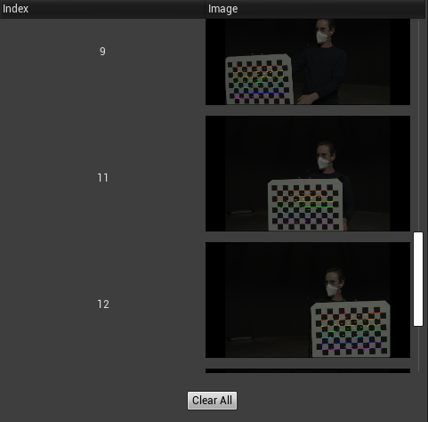
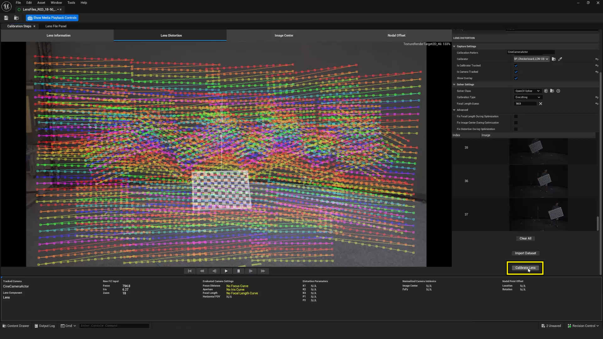
Move the checkerboard around the camera field of view and continue to click the image to capture more calibration pictures. Make sure to move the checkerboard's location enough times to cover the field of view with overlapping images, at different orientations, and different depths to increase the accuracy of the calibration.
Only move the checkerboard. Do not move the camera.
-
As you click in the viewport and add images to the data set, you may wish to delete any erroneous captures (for example, a capture with motion blur). To remove an image, click on the image in the list and hit the delete key.
This video demonstrates the approximate coverage required:
-
After collecting enough overlapping images to at least cover the complete field of view, click Calibrate Lens.
-
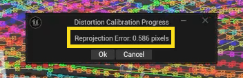
A dialog box with a message will appear. The reprojection error indicates the accuracy of the calibration.
-
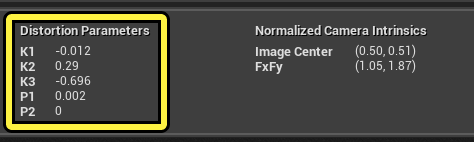
Check that the Distortion, Normalised Camera Intrinsics, and Nodal Point Offset have updated at the bottom of the lens file window.
Most lenses will have different distortion values at different focus distances. To make the most accurate Lens File for lens distortion, the process above should be repeated at different focus distances. For a full calibration of zoom lenses you will need to perform a number of calibrations at a range of focus distances across a range of focal lengths.
Confirm Calibration Result
You should notice that after a calibration, the virtual checkerboard is a closer visual match in the lens file viewport. However, it will still show a visual alignment discrepancy. This is because while the misalignment between real world and virtual checkerboard were taken into account during the calibration, the alignment is still incorrect on the checkerboard. Now that you have a calibrated lens and nodal offset, you can adjust the alignment of the checkerboard.
To adjust the checkerboard alignment, follow these steps:
-
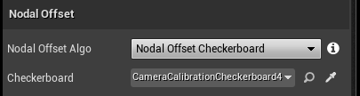
In the Lens File Asset Editor, switch to the Nodal Offset tab.
-
Set Nodal Offset Algo to Nodal Offset Checkerboard.
-
Set Checkerboard to your checkerboard actor.
-
-
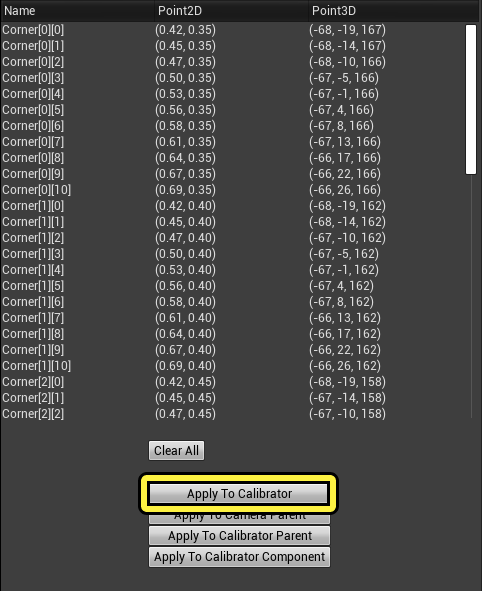
Click the image to populate all the corner data from the calibration.
-
Click Apply To Calibrator. This moves the checkerboard actor to the camera to match the physical checkerboard.
-
Under Viewport Settings, set Transparency to less than 1 to verify the checkerboard actor matches the physical checkerboard in the camera viewport.
The following video demonstrates using a transparency to overlay the virtual and video feeds to validate the accuracy of the calibration with the tracked checkerboard. Note that during this example we also offset the tracking data to align the video frames.
Optional Calibration Workflows
The following workflows can be used with the steps above to account for differences in your process.
Calibrating Lens Distortion Without Nodal Offset
This workflow can be useful in the absence of camera tracking or a tracked checkerboard, or if you want to carry out the nodal offset as a separate step.
When calibrating the lens distortion and node offset, follow step 1 with the following adaptations:
- Set the Calibration type to Distortion and Intrinsics
- Set Is Calibrator Tracked and Is Camera Tracked as appropriate
Calibrating Nodal Offset Without Lens Distortion
This workflow might be useful if you already have calibrated for lens distortion or because the lens has been remounted to the camera body or the camera tracking crown has been moved.
When calibrating the lens distortion and node offset, follow step 1 with the following adaptations:
- Set the Calibration type to Nodal offset
Improving or Manually Editing the Calibration
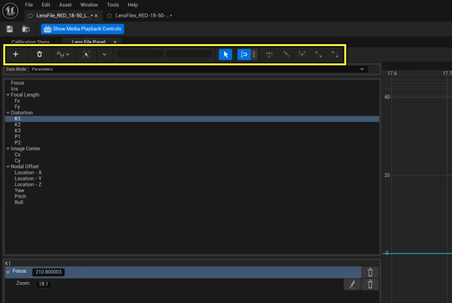
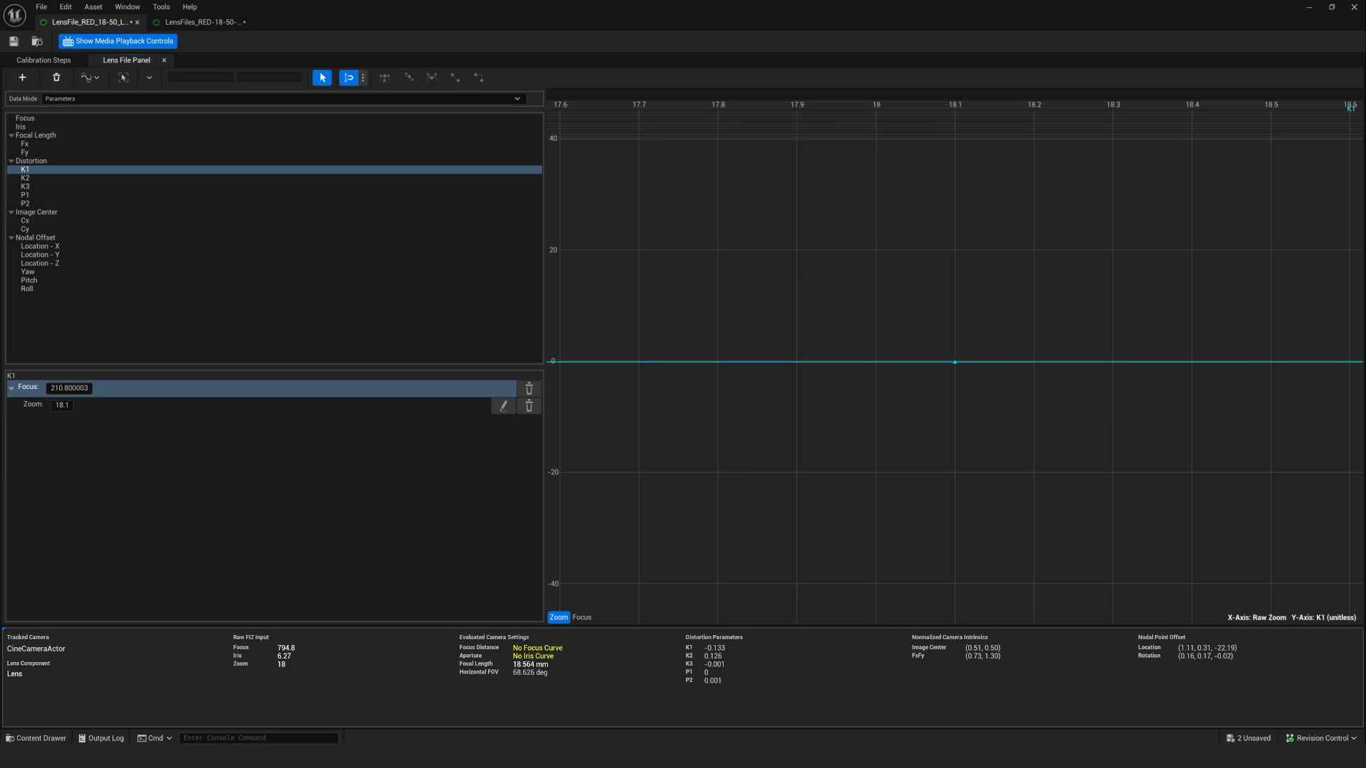
It is possible to manually tweak and edit the calibration. This is achieved using the Lens File Panel tab.
On this tab you will find a graph on the right and a list of parameters in the top left. Adjust the focus or zoom of the real world camera until you see a discrepancy, and then select the parameter that requires adjustment. Then, edit the point in the graph until you are satisfied with the result. You may find it helpful to remove the lens file panel to make adjustments while viewing the result in the lens file viewport update in real time.
Adjusting the interpolation between points can also fine-tune your calibration result.