
Goals
In this Quick Start guide, you will go through the steps to align an LED wall to your camera tracking with ArUco markers.
Objectives
-
Generate ArUco markers for your LED wall.
-
Preview the ArUco markers in the editor Viewport and the stage LED screens.
-
Use the ArUco markers to calibrate your LED wall.
1 - Required Setup
For this guide, you will use a production camera, an optical camera tracking system, and an AJA Kona 5 for source video input. In addition, you will need an existing LED wall configuration and a nDisplay Blueprint that matches your stage LED wall configuration. Follow the Rendering to Multiple Displays with nDisplay documentation to learn how to create your nDisplay Blueprint.
Before proceeding, follow the Camera Calibration for Production guide to make sure the lens distortion and nodal point offset of your camera are calibrated. This will create a Lens File Asset that will be used as part of the LED wall alignment with camera tracking.
The example in this guide is based on the Epic LA RnD stage LED wall setup.
Click image to expand.
2 - Generating the ArUco markers
-
Click Settings > Plugins to open the Plugins Menu.

-
Search for the LED Wall Calibration and the Live Link Over nDisplay plugins and enable them. Restart the editor.


-
In the Content Browser, search for your nDisplay stage actor Blueprint and double-click it to open it.

Click image to expand.
-
Select your first wall mesh from the Components panel and double-click the corresponding cluster from the Cluster panel. This will give you the selected display's resolution.
-
With the wall mesh selected, click + Add Component and search for and select Calibration Point. This will add a Calibration Point component as a child of your wall mesh.

-
Rename the Calibration point to ArUcoW1.

-
With the Calibration Point selected, go to the Details panel and scroll down to the Calibration section. Click Create ArUcos.

-
The ArUco Generation Options window will open.
-
Enter the Texture Width and Texture Height values that correspond to the wall viewport that ArUcos are being applied to.
-
Select the appropriate ArUco Dictionary from the list. In this example, the DICT_6x6_1000 dictionary is selected, which has 1000 unique ArUco symbols.
-
Enter the Marker ID that will be used as the starting ID for the ArUco markers that will be generated.
-
Enter the Place Modulus value. This value represents the number of LED panels that will be skipped when placing the ArUco markers. This is useful for working on a large LED wall, where you would use over 1000 unique ArUco symbols if they were to be placed on every LED panel. The default value is 2. Change this to 1 for smaller LED walls where one ArUco can be displayed on every panel. Using the default value of 2 will place an ArUco symbol on every second LED panel.
-
Click OK to generate the ArUco markers.

-
-
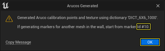
Select a location to save the texture and click OK. A confirmation window will appear that tells you which marker Id to start from for the next viewport. This will be remembered by UE, but can be adjusted in case you need to change the order. Click OK to confirm.

-
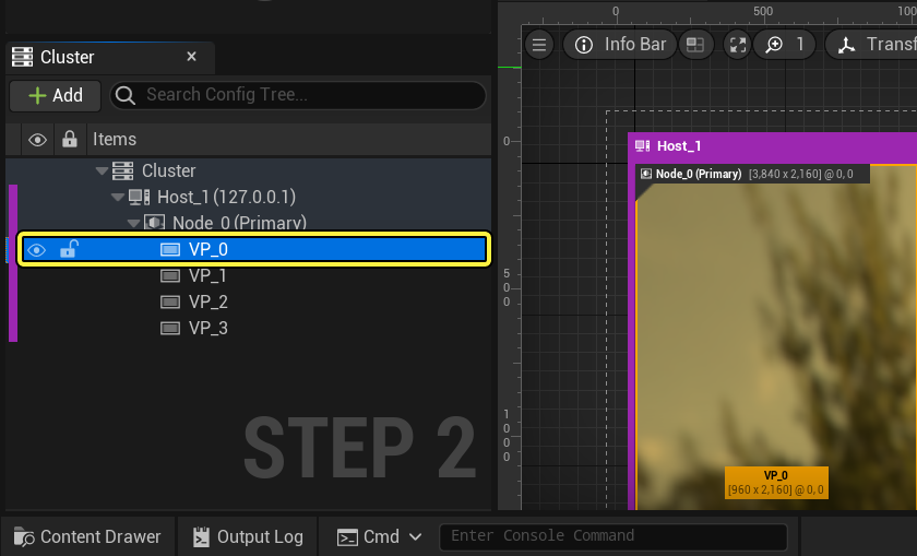
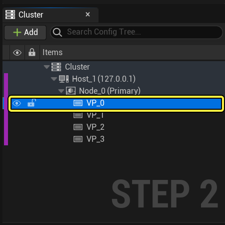
Select the Viewport to which the calibration point was applied in the Cluster tab.
-
Go to the Details panel on the right. Scroll down to the Texture Replacement section and select the generated texture as the Source Texture. Enable the Enable Viewport Texture Replacement checkbox.

-
Repeat steps 5 to 10 to add the ArUco markers to the remaining LED viewports.
-
In the Content Browser, double-click the nDisplay Blueprint to open it.

-
Click + Variable to create a new boolean variable and name it Replace_Viewport_Textures. Go to the Details panel and enable the Instance Editable checkbox.


-
Drag Replace_Viewport_Textures to the Event Graph and select Get Replace_Viewport_Textures to create a node.
-
Right-click in the Event Graph and search for and select Set Replace Texture Flag for All Viewports.
-
Connect the Event Tick node to the Set Replace Texture Flag for All Viewports node. Connect the Replace Viewport Textures node to the Replace pin of the Set Replace Texture Flag for All Viewports node.

-
Compile and Save the Blueprint.
-
To see the changes in the Preview Pane of the nDisplay Blueprint, select the nDisplay Blueprint and go to the Details panel. Scroll down to the Editor Preview section and enable the Replace Viewport Textures and Enable Editor Preview checkboxes. This will show the ArUco markers.


Click image to expand.
-
If you are using multiple render nodes, sync the project to the other computers now.
-
In the Outliner, select the nDisplay Blueprint and go to the Details panel. Scroll down to the Default tab and enable the Replace Viewport Textures checkbox. The ArUco markers will now appear on the LED wall.

Click image to expand.
-
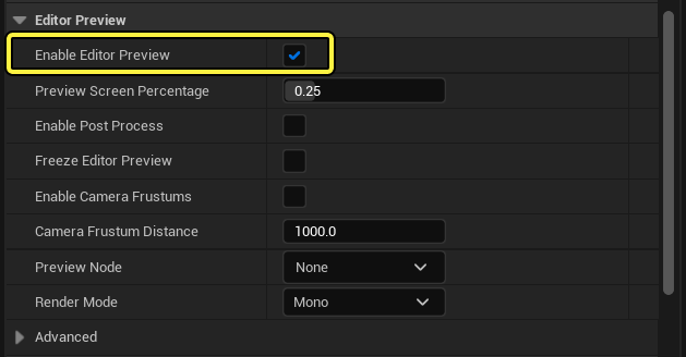
To see the ArUco markers in the Editor Viewport, scroll down to the Editor Preview section and enable the Enable Editor Preview checkbox.

Click image to expand.
-
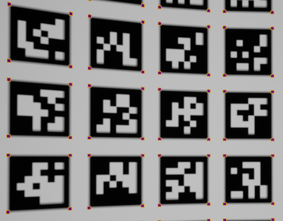
To check the alignment of the LED wall, it is helpful to see the points at the corners of the ArUco markers.
-
Select a Calibration Point that was created when the ArUcos were added.
-
Go to the Details panel and scroll down to the Calibration section. Enable the Visualize Points in Editor checkbox.
-
The Point Visualization Scale adjusts the scale of the markers on the mesh. The Visualization Shape dropdown changes the marker shapes between Cubes and Pyramids. Adjust these values to suit your needs.

-
-
Compile and Save the Blueprint.
-
In the Outliner window, select the nDisplay Blueprint and go to the Details panel. Scroll down to the Editor Preview section and enable the Enable Editor Preview checkbox.
This will allow the CG ArUcos to be displayed on the viewport mesh in the Lens file. Once the LED calibration is applied, the CG ArUcos will be overlaid on the live video feed from the camera that shows the ArUcos on the LED wall.
-
Place the tracked production camera and any other tracked objects under a Tracking Node. Parent the Tracking Node to the nDisplay Blueprint.
Section Results
You generated the ArUco markers and are now ready to use them as part of your Lens file to calibrate your LED wall.
3 - Calibrating your LED wall with the ArUco markers
-
In the Content Browser, double-click the Lens File that was created in the Camera Calibration for Production guide to open it. The Lens File should be attached to the camera under the LiveLinkController streaming the FIZ data.
-
Click the Nodal Offset tab.
Click image to expand.
-
Go to the Viewport Settings and set the Transparency to 0. This will turn off the CG overlay of the ArUco markers that are displayed in the Editor.

-
Go to the Nodal Offset section and set the Nodal Offset Algo to Nodal Offset ArUco markers
-
Set the Calibrator to the nDisplay Blueprint.
-
Enable the Show Detection checkbox. This will capture an image each time the Viewport is clicked and will be used to gather calibration points of the ArUco Markers.

-
-
Point the production camera at the LED wall that is displaying the ArUcos markers. You will now collect images of the ArUco markers across the LED wall. Click the mouse inside the viewport to capture an image. A preview of the captured image will be displayed. Click the OK button.
Click image to expand.
-
Repeat the previous step multiple times to capture several images across the LED wall. You will see the captured images displayed under the Nodal Offset section.
-
Once you have captured enough samples across the LED wall, click on Apply to Camera Parent button. This will offset the Tracking Origin previously created and the tracked production camera below it.
-
To check the alignment of the LED wall, set the Transparency to 0.5. This will show the CG ArUcos applied to the LED wall mesh overlaying the ArUcos on the physical LED wall. Both sets of ArUco markers should now be right on top of each other. If not, the virtual LED mesh does not match the physical LED mesh.
Section Results
You calibrated your stage LED wall using the ArUco markers.